An overview of the crane 3.1-1
3.1. An overview of the crane
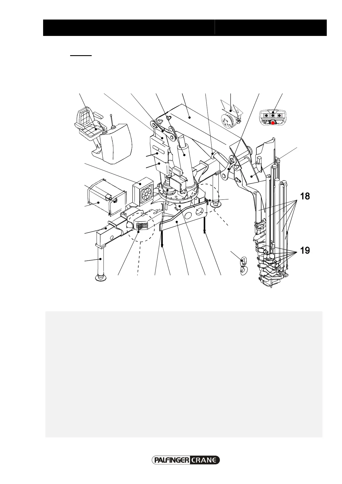
3.1-1 Set-up
The crane displayed in the following is an example and shows crane components that can optionally
be on your crane depending on model and crane type.
2A
2B
1
1
3 4245 4
6
8
7
9
10
1
21
22
20
1 Control unit crane support 13 Main boom
2A Control unit - control valve side (Side A) 14 Hinged arm cylinder
2B Control unit - opposite side (Side B) 15 Rope winch
3 Slewing mechanism, unlimited 16 Toggle
4 Shackle bolts 17 Hinge pin
5 Balance 18 Hydraulic cylinder extendable arms
6 Support cylinder 19 Hinge arm and mechanical extensions
7 Outrigger 20 Oil cooler
8 Hydraulic fluid tank 21 Emergency control stand
9 Hydraulic fluid level indicator /
Temperature indicator
22 Display and circuit element
10 Hook 23 Remote control console (transmitter)
11 Crane pillar 24 Base
12 Hydraulic elevating cylinder 25 Top seat