49
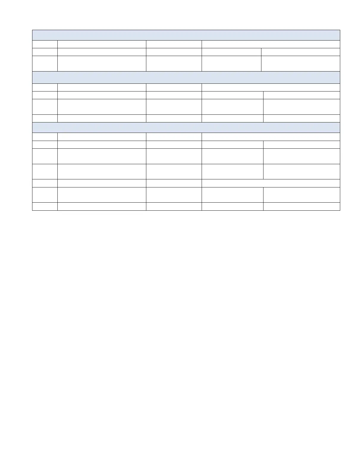
Table 12: Remote Control I/O Chart
Analog I/O Connector Circuits
Speed set point input
0-10VDC
Discrete I/O Connector Circuits
Allegro I/O Connector Circuits
Norma/Locked Mode switch
input
Speed control switch input
Open=Local speed
adjustment
Closed=Remote speed
control
Speed set point input
4-20 mA
The analog speed control input 0-10 V (pins 4 and 5 of ANALOG I/O connector) has an
impedance of 500 kOhm. The safe input voltage range is -0.5 V to +15 V
For the analog output 4-20 mA (pins 2 - 3 of ANALOG I/O connector and pins 11 – 12 of
ALLEGRO I/O connector) the MAX load resistance should not exceed 500 Ohm.
For equipment safety and to avoid possible excess noise on the speed control input signal (pins
4, 5 of ANALOG I/O connector) it is recommended to include an Isolation amplifier in the design
of the 0-10 VDC remote control external circuitry.
IMPORTANT: Avoid having in use simultaneously remote cable in Allegro connector and
standard remote cables (discrete and analog connectors) to prevent potential interference of
some of I/O signals.
IMPORTANT: External connectors and cables are rated 300 V to 600 V. For all external
communication signals, normally working voltage does not exceed 24 V by design.
Per safety requirements external equipment intended for connection to signal inputs, signal
outputs or other connectors shall comply with the relevant product standard e.g. IEC 60950-1 or
IEC 62368-1 for IT-equipment and the IEC 61010-1-series for laboratory equipment so as to
provide proper isolation between high voltage and low voltage circuits.
 Loading...