Page 33 of 48
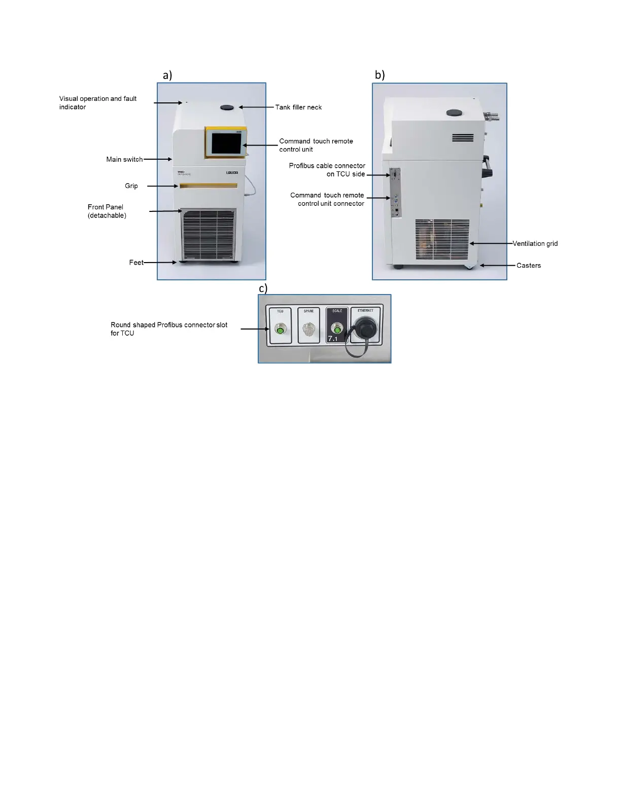
Figure 25: Connection of PROFIBUS cable between TCU and iCELLis 500+ control system –
a) Front of TCU, including Interface panel, b) Side of TCU with Interface panel,
c) Connections at the rear of iCELLis 500+ control system.
Follow Figure 26 to assemble and install the TCU.
Remove the TCU unit from the crate and install it on a flat surface (Figure 26a-b). Place the command
touch panel in its designated place on the TCU and connect its cable to the right side of the TCU as
shown in (Figure 26c-d).
Take out the Profibus cable from crate and connect one end of the cable to right side of the TCU and
other end to back of the iCELLis 500+ control system, tighten the connector on the TCU using a flat
screwdriver, please refer to Figure 26e-f.
Confirm the TCU power switch is in the OFF position and connect the power cable to the appropriate
voltage supply (230Vac - 50Hz or 120Vac - 60Hz). Refer to the user manual of the TCU for power
options. Refer to Figure 26h-i.
Locate the barbed connectors from the crate and remove the nuts from the back side of the TCU
IN/OUT lines. Refer to Figure 26j-k. Refer to Figure 26l-o to put nuts on the connectors and connect the
combination to the IN/OUT line of TCU.
 Loading...