69
E
N
G
L
I
S
H
54
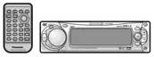
CQ-DVR592U
68
Electrical Connections
CQ-DVR592U
E
N
G
L
I
S
H
53
Caution:
≥ This product is designed to operate with a 12 V DC, negative ground battery system.
≥ To prevent damage to the unit, be sure to follow the connection diagram below.
≥ Remove approx.
1
⁄4z (5 mm) of protective covering from the ends of the leads before connecting.
≥ Do not insert the power connector into the unit until the wiring is completed.
≥ Be sure to insulate any exposed wires from a possible short-circuit from the car chassis. Bundle all
cables and keep cable terminals free from touching any metal parts.
≥ Remember, if your car has a drive computer or a navigation computer, the data of its memory may
be erased when the battery terminals are disconnected.
≥
The remote control unit does not work when it is facing the remote control sensor on the connected monitor.
❐ Accessories used for wiring
Wiring Diagram
Q’ty
1
ItemNo.
6
Power Connector
Example Combination
≥Color LCD Monitor
(CY-VMX6800U, option)
6
Power connector
(Orange)
(Blue/Yellow Stripe)
(Red)
(Yellow)
(Black)
(Blue/White Stripe)
(Brown/White Stripe)
(Dark Blue)
(Green/Yellow Stripe)
ANT-CONT MAX0.1A
AMP-CONT MAX0.1A
(
TWIN CD
•
C-CONT
)
Not used.
Radio antenna input
CQ-DVR592U
Changer control cord
R (Red)
L (White)
R (Red)
L (White)
(Red)
(White)
R (Red)
L (White)
R (Red)
L (White)
Video (Yellow) Video (Yellow)
(R)
(L)
(R)
(L)
To
Front Speaker
To
Rear Speaker
PRE OUT Cord (Front)
REAR AUDIO OUT Cord
VIDEO OUTPUT Cord
PRE OUT Cord (Rear)
Subwoofer Cord
AUX-INPUT Cord
CD CHANGER INPUT Cord
(Gray)
(Gray/Black Stripe)
(White)
(White/Black Stripe)
(Violet)
(Violet/Black Stripe)
(Green)
(Green/Black Stripe)
Speaker Lead
Speaker Lead
Speaker Lead
Speaker Lead
+
-
+
-
+
-
+
-
RCA Cord
(option)
RCA Cord (option)
OPTICAL OUT
NAVI MUTE
PARKING BRAKE
Resistor (1 kΩ)
ACC
BATTERY 15 A
Fuse (15 A)
FRONT
REAR
AUX-IN
S
.
W-OUT
CD.C-IN
FRONT R
FRONT L
REAR L
REAR R
Note:
≥
The power antenna extends automatically when the AM/
FM radio mode is selected.
Motor antenna relay control lead
(To motor antenna) (Max. 0.1 A)
This lead is not intended for use with switch actuated power antenna.
ACC power lead
To ACC power, _12 V DC.
Battery lead
To the battery, continuous _12 V DC.
Ground lead
To a clean, bare metallic part of the car chassis.
Side brake (parking brake)
connection lead
Be sure to wire the side brake (parking brake) for
safety and preventing accidents. ( page 70)
External amplifier control lead
(Max. 0.1 A)
This lead is for connection to the power amplifier.
Note:
≥
This lead is used for power control when an external power
amplifier is connected. The power supply of a power amplifier
will be activated when turning on the power of this unit.
Note:
≥
Not used
Insulate this lead with vinyl tape .
R (Red) R (Red)
L (White) L (White)
L (White)
R (Red)
Video (Yellow)
L (White)
(Monaural)
Connect this cord when the monitor
is to be installed on the back seat.
REAR AUDIO-OUT
Not used.
Note:
≥
Insulate this lead with vinyl tape .
VTR1-IN
Power connector
Power socket
VTR1
input lead
CY-VMX6800U
(option)
R (Red)
Video (Yellow)
VIDEO-CONT
VIDEO-OUT
 Loading...