Emergency operation
•
• •
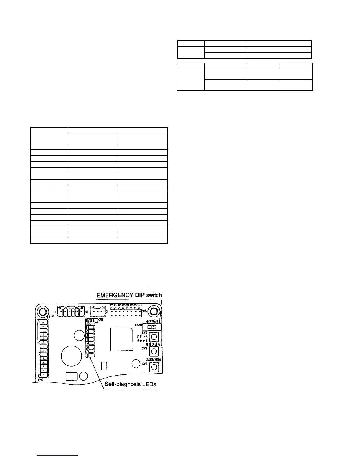
• Emergency operation of outdoor unit
Emergency operation can be carried out by setting the
DSW1 switch on the printed circuit board inside the
outdoor unit to the EMERGENCY position. However,
emergency operation is only carried out when an
abnormality is detected by the indoor/outdoor
temperature thermistors.
The resistance values of each thermistor are measured
as shown in the table below to determine if there is an
abnormality.
Thermistor resistance table
Temperature Resistance value (k
Ω
)±5%
Room temperature
thermistor
Pipe temperature
thermistor
-20°C 205.8 197.8
-10°C 114.6 111.9
-5°C 87.3 85.4
0°C 67.0 65.8
5°C 51.8 51.0
10°C 40.4 39.9
15°C 31.7 30.7
20°C 25.1 25.0
25°C 20.0 20.0
30°C 16.1 16.0
40°C 10.4 10.6
50°C 6.9 7.1
60°C 4.7 4.9
70°C ___ 3.5
80°C ___ 2.5
90°C ___ 1.8
100°C ___ 1.4
The pipe temperature thermistor resistance value are
the same for the indoor and outdoor units.
<When a thermistor abnormality is judged to have
occurred>
−
− −
− Set only the thermistor which shows an abnormality
to the condition shown in the table below to carry out
emergency operation
Thermistor Cooling mode Heating mode
Indoor unit Room temperature Fixed at 25°C
Room temperature Shorted Open
Thermistor Cooling mode Heating mode
Outdoor unit Discharge
temperature
Open Shorted
Heat exchanger
outlet temperature
Shorted Open
−
− −
− Refer to the circuit diagram for the connection
locations for each thermistor.
−
− −
− If there is an abnormality in the room temperature
thermistor, the temperature will be fixed at 25°C
regardless of the remote control unit display.
NOTE:
−
− −
− Any abnormalities detected by the temperature
thermistors are ignored during emergency operation,
so that long-term operation in this mode should be
avoided.
−
− −
− After emergency mode operation has been
completed and normal operation is to be resumed,
turn the power supplies for the indoor and outdoor
units off and return the DIP switch to the NORMAL
position.
−
− −
− Self-diagnosis LEDS 4 to 6 will flash during
emergency operation.
25 EMERGENCY OPERATION
58