– 40 –
MAC9512086C2
CS-A73KE
Servicing Information
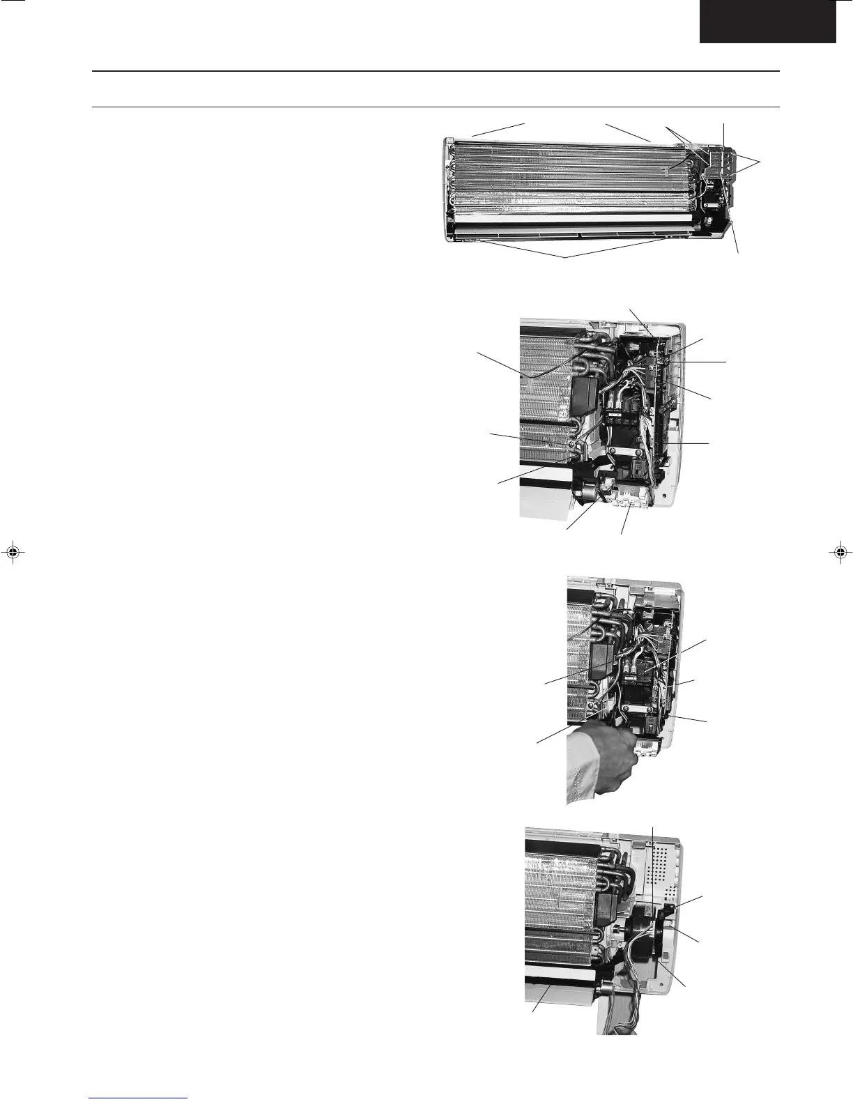
● Inspection points for the Indoor Electronic Controller
1. The Electronic Controller, a signal Receiver and an
Indicator (Fig. 2) can be seen by the below steps:
– Remove the 2 caps and 2 screws at the bottom
of the front grille. (Fig. 1)
– Remove the front grille by releasing the 2 hooks
at the top of the front grille. (Fig. 1)
– Remove the control board cover by releasing
the 2 tabs at left, 1 tab on top and 2 more tabs at
right side of the control board cover. (Fig. 1)
2. To remove the Electronic Controller, release the
hook that holding the electronic controller. (Fig. 2)
● Indoor Fan Motor removal procedure :-
1. Remove the control board by:-
– Releasing CN-C (GRN) connector
– Releasing CN-FM (GRN) connector
– Releasing CN-STM connector
– Remove the earth wire screw
– Release the intake air sensor
– Release the piping sensor
– Unhook and release the terminal board.(Fig. 3)
– Remove the right and left screws.(Fig. 3)
– Then remove the control board by pressing
down the hook at the left and press up the right
hook. (Fig. 3)
2. Remove the Fan Motor by :-
– Release the fan motor leadwire by pressing the
hook at the center of the connector. (Fig. 4)
– Then remove the particular piece that holding
the fan motor by pressing the tab. (Fig. 4)
– Remove the discharge grille and then the drain
hose. (Fig. 4)
➞
➞
Tabs
Tab
Control Board
Cover
Release hooks
Tabs
Remove 2 caps and 2 screws
Fig. 1
CN-STM
Hook
CN-C (GRN)
CN-FM
(GRN)
Electronic Controller
Intake Air
Sensor
Earth Wire
Screw
Piping
Sensor
Fig. 2
Signal
Receiver
Indicator
Fig. 4
Fan motor
Tab
Particular
piece
Discharge
grille
Fan motor connector
Screw
(remove)
➞
Left hook
(press down)
➞
Screw
(remove)
right hook
(press up)
Terminal Board
(Unhook)
Fig. 3
}
(Fig. 2)
Untitled-14 6/19/00, 11:18 AM40