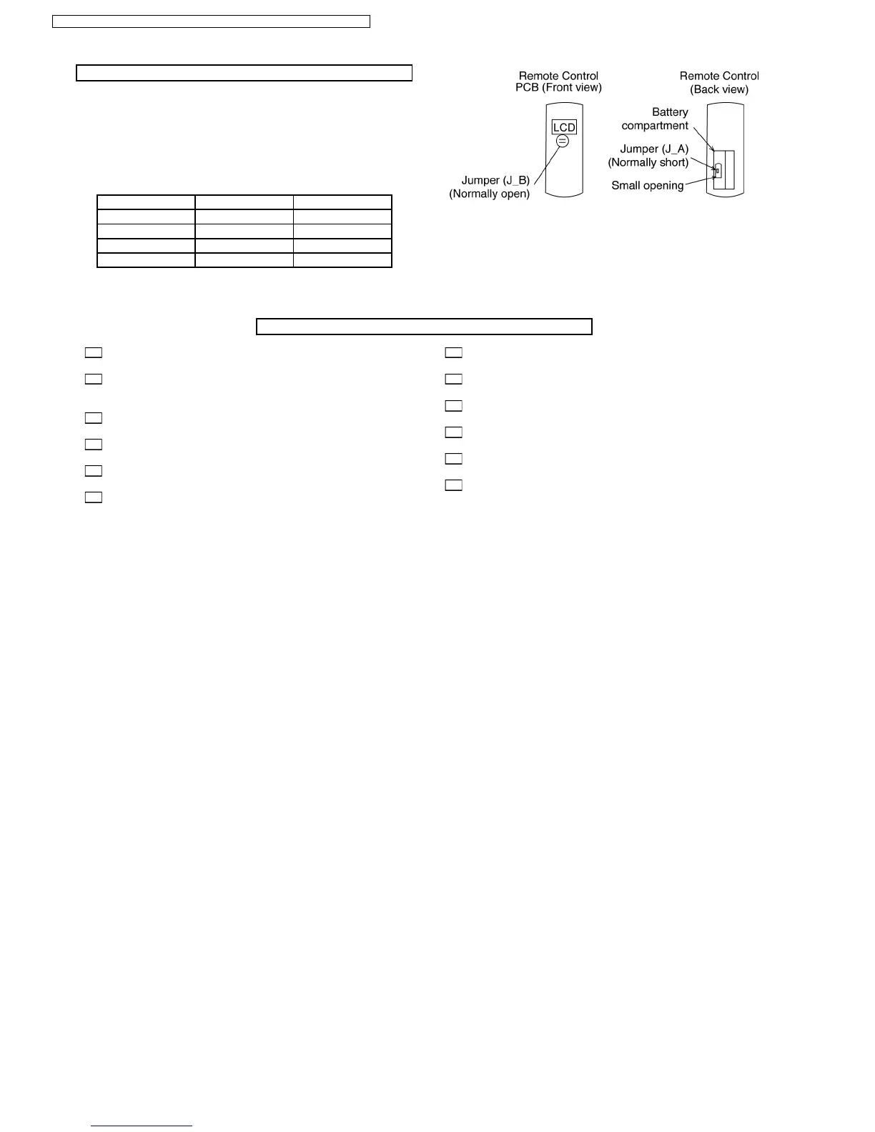
REMO-CON NO. CHANGE IN REMOTE CONTROL
1. Remove the batteries from the battery compartment of the
Remote Control.
2. On the left side of the battery compartment, there is a small
opening in the centre in which Jumper (J_A) can be seen.
In the accepted Remo-Con PCB shown beside, Jumper
(J_B) can be seen.
J_A J_B Remo-Con No.
Short Open A (Default)
Open Open B
Short Short C
Open Short D
Is there any gas leakage at flare nut connections?
Has the heat insulation been carried out at flare nut
connections?
Is the connecting cable being fixed to the terminal board
firmly?
Is the connecting cable being clamped firmly?
Is the drainage OK?
Is the earth wire connection properly done?
Is the cooling operation normal?
Is the indoor unit property secured to the installation plate?
Is the power supply voltage complied with rated value?
Is there any abnormal sound?
Is the thermostat operation normal?
Is the remote control’s LCD operation normal?
CHECK ITEMS
62
CS-E15DTEW CU-E15DBE / CS-E18DTEW CU-E18DBE / CS-E21DTES CU-E21DBE