EasyManua.ls Logo

Panasonic CS-E24DKE User Manual

Panasonic CS-E24DKE
94 pages
To Next Page IconTo Next Page
Page #1 background imageLoading...
Page #1 background image
1 Features 2
2 Functions
3
2.1. Remote Control
3
2.2. Indoor Unit
4
2.3. Outdoor Unit
6
3 Product Specifications
7
3.1. CS-E24DKE CU-E24DKE
7
4 Dimensions
9
4.1. Indoor Unit & Remote Control
9
4.2. Outdoor Unit
10
5 Refrigeration Cycle Diagram
11
6 Block Diagram
12
7 Wiring Diagram
13
8 Operation Details
14
8.1. Basic Function
14
© 2005 Panasonic HA Air-Conditioning (M) Sdn Bhd
(11969-T). All rights reserved. Unauthorized copying
and distribution is a violation of law.
CS-E24DKE CU-E24DKE
8.2. Protection Control Features 31
9 Operating Instructions
41
10 Installation And Servicing Air Conditioner Using R410A
47
10.1. Outline
47
10.2. Tools For Installing/Servicing Refrigerant Piping
48
10.3. Refrigerant Piping Work
52
10.4. Installation, Transferring, Servicing
54
11 Installation Instructions
58
11.1. Safety Precautions
58
11.2. Indoor Unit
61
11.3. Outdoor Unit
65
12 Servicing Information
68
12.1. Distinction Of Lead Free (PbF) Printed Circuit Board
68
12.2. Troubleshooting
68
12.3. Breakdown Self Diagnosis Function
70
Air Conditioner
CONTENTS
Page Page
Order No. MAC0501002C2

Table of Contents

Question and Answer IconNeed help?

Do you have a question about the Panasonic CS-E24DKE and is the answer not in the manual?

Panasonic CS-E24DKE Specifications

General IconGeneral
BrandPanasonic
ModelCS-E24DKE
CategoryAir Conditioner
LanguageEnglish

Summary

1 Features

2 Functions

2.1. Remote Control

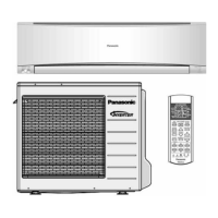
Explains the functions and settings of the remote control.

2.2. Indoor Unit

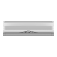
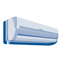
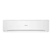
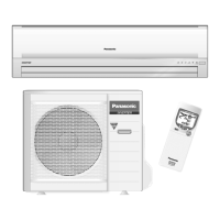
Describes the functions and indicators of the indoor unit.

2.3. Outdoor Unit

Describes the functions and controls of the outdoor unit.

3 Product Specifications

3.1. CS-E24DKE CU-E24DKE

Details technical specifications like capacity, airflow, and electrical data.

4 Dimensions

4.1. Indoor Unit & Remote Control

Provides dimensional drawings and measurements for the indoor unit and remote control.

4.2. Outdoor Unit

Provides dimensional drawings and measurements for the outdoor unit.

5 Refrigeration Cycle Diagram

6 Block Diagram

7 Wiring Diagram

8 Operation Details

8.1. Basic Function

Explains inverter control and temperature shifting processes.

8.1.2. Compressor Operation Frequency

Details compressor frequency control based on temperature.

8.1.3. Cooling Operation

Explains thermostat control logic for cooling operation.

8.1.10. Quiet Operation

8.1.10.1. Quiet operation under Soft Dry operation

Details quiet operation for soft dry mode.

8.1.10.2. Quiet operation (Heating)

Details quiet operation for heating mode.

Timer Controls

8.1.12. Delay ON Timer Control

Explains the function and operation of the delay ON timer.

8.1.13. Delay OFF Timer Control

Explains the function and operation of the delay OFF timer.

8.1.18. Ionizer Operation

8.1.18.1. Ionizer Problem Detection Control

Details ionizer problem detection and control.

8.1.18.2. Ionizer Operation case study

Provides a case study for ionizer operation.

8.2. Protection Control Features

8.2.1. Protection Control For All Operations

Explains various protection controls for all operations.

8.2.1.4. IPM (Power transistor) Prevention Control

Explains IPM overheating and DC peak current protection.

8.2.1.5. Compressor Overheating Prevention Control

Details compressor frequency regulation by top temperature.

8.2.1.6. Low Pressure Prevention Control (Gas Leakage Detection)

Explains compressor stop due to low pressure.

8.2.2. Protection Control For Cooling & Soft Dry Operation

8.2.2.1. Outdoor Air Temperature Control

Explains frequency regulation by outdoor air temperature.

8.2.2.2. Cooling Overload Control

Details pipe temperature limits and compressor stop.

8.2.3. Protection Control For Heating Operation

8.2.3.1. Anti Cold Draft Control

Explains fan speed variation based on heat exchanger temperature.

8.2.3.2. Intake Air Temperature Control

Explains compressor frequency based on intake air temperature.

8.2.3.3. Outdoor Air Temperature Control

Explains frequency regulation by outdoor air temperature.

8.2.3.4. Overload Protection Control

Explains frequency regulation by indoor heat exchanger temperature.

8.2.3.5. Outdoor Temperature Control

Explains control based on outdoor temperature.

8.2.3.6. Deice Control

Details detection methods and time chart for deice operation.

11 Installation Instructions

11.1. Safety Precautions

General safety precautions for installation.

11.2. Indoor Unit

Covers indoor unit installation procedures.

11.3. Outdoor Unit

Covers outdoor unit installation procedures.

11.3.5. CONNECT THE CABLE TO THE OUTDOOR UNIT

Instructions for connecting cables to the outdoor unit.

11.3.6. PIPE INSULATION

Instructions for pipe insulation.

12 Servicing Information

12.1. Distinction Of Lead Free (PbF) Printed Circuit Board

How to distinguish lead-free PCBs and handling precautions.

12.2. Troubleshooting

Guides for diagnosing refrigeration cycle system issues.

12.3. Breakdown Self Diagnosis Function

How to access and use the breakdown self-diagnosis function.

12.4. Remote Control

• Remote Control Reset

Procedure to reset the remote control.

• Changing the wireless remote control transmission code

How to change transmission codes for multiple units.

12.5. Indoor Electronic Controllers Removal Procedures

12.6. Cross Flow Fan and Indoor Fan Motor Removal Procedures

12.7. Outdoor Electronic Controller Removal Procedure

13 Technical Data

Operation characteristics

Cooling and heating characteristics graphs.

14 Exploded View (Indoor Unit)

14.1. CS-E24DKE

Exploded view diagram of the indoor unit.

15 Replacement Parts List (Indoor Unit)

15.1. CS-E24DKE

List of replacement parts for the indoor unit.

16 Exploded View (Outdoor Unit)

16.1. CU-E24DKE

Exploded view diagram of the outdoor unit.

17 Replacement Parts List (Outdoor Unit)

17.1. CU-E24DKE

List of replacement parts for the outdoor unit.

18 Electronic Circuit Diagram

18.1. Indoor Unit

Schematic diagram of the indoor unit's electronic control.

18.2. Outdoor Unit

Schematic diagram of the outdoor unit's electronic control.

Sensor Characteristics

Fig. 1

Resistance vs. temperature graphs for sensors.

Fig. 2

Voltage vs. temperature graphs for sensors.

Fig. 3

Voltage vs. temperature graphs for sensors.

Fig. 4

Voltage vs. current graph for total running current.

Fig. 5

Resistance vs. temperature graph for compressor temp sensor.

Fig. 6

Voltage vs. temperature graph for compressor temp.

How to use electronic circuit diagram

Remote Control Circuit Diagram

18.4. Print Pattern

Indoor Unit Printed Circuit Board

Print pattern of the indoor unit's main PCB.

Outdoor Unit Printed Circuit Board

Print pattern of the outdoor unit's main PCB.

Related product manuals