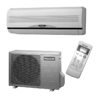
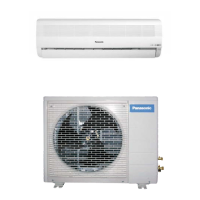
SELECT THE BEST LOCATION
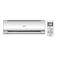
INDOOR UNIT
There should not be any heat source or steam near the
unit.
There should not be any obstacles blocking the air
circulation.
A place where air circulation in the room is good.
A place where drainagecanbeeasily done.
A place where noise prevention is taken into
consideration.
Do not install the unit near the door way.
Ensure the spaces indicated by arrows from the wall,
ceiling, fence or other obstacles.
Recommended installation heig
ht for indoor unit
shall
be
atleast 2.5 m.
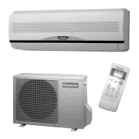
OUTDOOR UNIT
Ifan awning is built over the unit to prevent direct
sunlight or rain, be careful thatheatradiation from the
condenser is not obstructed.
There should not be any animalorplant which could
be
affected by hot air discharged.
Keep the spaces indicated by arrows fromwall, ceiling,
fence or other obstacles.
Do not place any obstacles which maycause a short
circuit of
the discharge air.
If piping length is over the common length, additional
refrigerant should be added as shown in the table.
Indoor/Outdoor Unit Installation Diagram
- 27 -
Attached accessories.
No. Accessories part Qty.
1
2
3
4
Installation plate
Installation plate fixing
screw
Remote control
Battery
1
5
1
2
Indoor/Outdoor Unit Installation Diagram
About 1.1 m
Piping direction Attention not to
bend up drain hose
Length of power supply cord
Right
Right Bottom
Right Rear
Left
Rear
Left Bottom
Left
(Front side)
About 1.8 m
<
<
<
<
(Left and right are identical)
This illustration is for explanation purposes only.
The indoor unit will actually face a different way.
Installation plate
1
Sleeve ( )
BushingSleeve ( )
Putty (Gum type sealer) ( )
Vinyl tape (Wide) ( )
Apply after carrying out a
drainage test.
To c arry out the drainage
test, remove the air filters
and pour water into the heat
exchanger.
Saddle ( )
Additionaldrain hose ( )
Bend the pipe as closely on
the wall as possible, but be
careful that it doesn't break.
Installation parts you
should purchase ( )
1/4" Liquid side piping ()
1
0c
m
o
r
mo
r
e
Gas side piping( )3/8"
1
00 cm
or
m
or
e
30
c
m
or
m
o
re
5cm
or more
Insulation of piping connections
Carry out insulation
after checkingfor
gasleaks and
secure with vinyl
tape.
Vinyl tape
5cm
or more
10 c
m
or m
or
e
Type designation 245 IEC 57
or heavier cord
Connecting cable
2
3-CORE WIRE/1.5mm ()
CS-PV9DKE / CU-PV9DKE / CS-PV12DKE / CU- PV12DKE
1
0
cm
or
mor
e
30
c
m
or
mo
r
e
10
0
c
m
o
r
mo
re
1
0
c
m
o
r
m
or
e
CU-PV9DKEK
CU-PV12DKE
9.2.1. SELECT THE BEST LOCATION
(Refer to "Select the best location"
section)
9.2. INDOOR UNIT
Model
PV9DKE
PV12DKE
Piping size
Max. Piping
Length
(m)
10
15
Common
Length
(m)
7.5
7.5
Max.
Elevation
(m)
5
5
Additional
Refrigerant
(g/m)
10
15
Gas
3/8"
3/8"
Liquid
1/4"
1/4"
F
A
N