EasyManua.ls Logo

Panasonic CU-C7BKP6 User Manual

Panasonic CU-C7BKP6
83 pages
To Next Page IconTo Next Page
Page #1 background imageLoading...
Page #1 background image
1 Features 2
2 Functions
3
3 Product Specifications
6
4 Dimensions
16
5 Refrigeration Cycle Diagram
18
6 Block Diagram
19
7 Wiring Diagram
20
8 Operation Details
21
9 Operating Instructions
29
10 Installation Instructions
34
© 2001 Matsushita Air-Conditioning Corp. Sdn. Bhd.
(183914D). All rights reserved. Unauthorized copying
and distribution is a violation of law.
CS-C7BKP CU-C7BKP5
CS-C7BKP CU-C7BKP6
CS-C9BKP CU-C9BKP5
CS-C9BKP CU-C9BKP6
CS-C12BKP CU-C12BKP5
CS-C12BKP CU-C12BKP6
11 2-way, 3-way Valve 45
12 Servicing Information
58
13 Troubleshooting Guide
62
14 Technical Data
64
15 Exploded View
68
16 Replacement Parts List
69
17 Exploded View
71
18 Replacement Parts List
72
19 Electronic Parts List
75
20 Electronic Circuit Diagram
76
Room Air Conditioner
CONTENTS
Page Page
Order No. MAC0107024C0
E25
Question and Answer IconNeed help?

Do you have a question about the Panasonic CU-C7BKP6 and is the answer not in the manual?

Panasonic CU-C7BKP6 Specifications

General IconGeneral
BrandPanasonic
ModelCU-C7BKP6
CategoryAir Conditioner
LanguageEnglish

Summary

1 Features

2 Functions

Remote Control

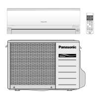
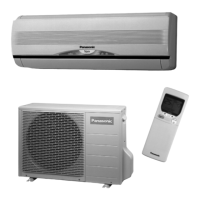
Describes the functions and operation of the remote control unit.

3 Product Specifications

4 Dimensions

5 Refrigeration Cycle Diagram

6 Block Diagram

7 Wiring Diagram

Power Supply Cord and Destination

Information on power supply cords and their destinations.

Resistance of Indoor Fan Motor Windings

Resistance values for indoor fan motor windings.

Resistance of Outdoor Fan Motor Windings

Resistance values for outdoor fan motor windings.

Resistance of Compressor Windings

Resistance values for compressor windings.

8 Operation Details

8.1. Cooling Mode Operation

Details operation of the air conditioner in cooling mode according to remote control settings.

8.2. Soft Dry Mode Operation

Explains the unit's operation in Soft Dry mode, including fan speed and cycle control.

8.4. Automatic Mode Operation

Details automatic mode determination based on indoor temperature and settings.

8.6. Powerful Mode Operation

Explains powerful mode for quickly achieving the set temperature.

8.9. Indoor Fan Speed Control

Explains auto and manual fan speed adjustment methods.

8.10. Vertical Airflow Direction Control

Details auto and manual control for vertical airflow direction louvers.

9 Operating Instructions

SAFETY PRECAUTIONS

Important safety precautions to follow before operating the unit.

Installation Precautions

Precautions related to the installation process to ensure safety.

Operation Precautions

Precautions to be observed during the normal operation of the unit.

NAME OF EACH PART

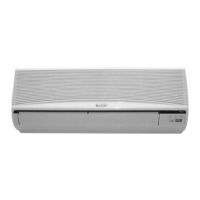
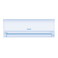
Identifies and labels the different parts of the indoor and outdoor units.

10 Installation Instructions

10.1. Safety Precautions

Crucial safety precautions to be followed before and during installation.

10.2. INDOOR UNIT

Procedures and guidelines for installing the indoor unit.

10.3. OUTDOOR UNIT

Procedures and guidelines for installing the outdoor unit.

10.3.4. (a) EVACUATION OF THE EQUIPMENT (FOR EUROPE & OCEANIA DESTINATION)

Detailed procedure for evacuating air from the system for specific regions.

11 2-way, 3-way Valve

2-way Valve (Liquid Side)

Describes the 2-way valve on the liquid side, its positions and uses.

3-way Valve (Gas Side)

Describes the 3-way valve on the gas side, its positions and uses.

11.1. Evacuation of the Equipment (For Europe & Oceania Destination)

11.1.1. Evacuation of Installation

Procedure for evacuating air from the indoor unit and piping during installation.

11.1.2. Pumping down

Procedure for pumping down refrigerant during operation or servicing.

11.1.6. Gas charging

Procedure for charging refrigerant into the system after evacuation.

11.2. Air Purging of the Piping and Indoor Unit

11.2.1. Air purging (Installation)

Steps for purging air from the piping and indoor unit during installation.

11.2.6. Gas charging (After Evacuation)

Gas charging procedure after evacuation, after the unit has been installed.

12 Servicing Information

12.1. Indoor Electronic Controllers Removal Procedures

Steps to remove and replace indoor electronic controller components.

12.2. Indoor Fan Motor and Cross Flow Fan Removal Procedures

Procedures for removing the indoor fan motor and cross flow fan.

13 Troubleshooting Guide

13.1. Refrigeration cycle system

Guide to diagnosing malfunctions related to the refrigeration cycle.

Call the Dealer Immediately

Critical conditions requiring immediate dealer contact.

14 Technical Data

Thermostat characteristics

Characteristics of the thermostat in cooling and soft dry modes.

Sensible Capacity Chart

Charts detailing sensible capacity based on various temperature conditions.

15 Exploded View

16 Replacement Parts List

17 Exploded View

18 Replacement Parts List

19 Electronic Parts List

20 Electronic Circuit Diagram

SCHEMATIC DIAGRAM 1/3

First part of the electronic circuit diagram for the air conditioner.

SCHEMATIC DIAGRAM 2/3

Second part of the electronic circuit diagram for the air conditioner.

SCHEMATIC DIAGRAM 3/3

Third part of the electronic circuit diagram for the air conditioner.

How to use electronic circuit diagram

Guide on how to interpret and use the provided electronic circuit diagrams.

TIMER TABLE

Table summarizing timer functions, times, and test modes.

20.1. REMOTE CONTROL

Detailed schematic of the wireless remote control circuit.

20.2. PRINT PATTERN INDOOR UNIT PRINTED CIRCUIT BOARD TOP VIEW

Top view print pattern of the indoor unit's printed circuit board.

20.3. PRINT PATTERN INDOOR UNIT PRINTED CIRCUIT BOARD BOTTOM VIEW

Bottom view print pattern of the indoor unit's printed circuit board.

Related product manuals