35
8.2. When Replacing the Main PCB
After replacing the MAIN PCB, be sure to achieve adjustment.
The adjustment instruction is available at “software download” on the “Support Information from NWBG/VDBG-AVC” web-site in
“TSN system”, together with Maintenance software.
8.3. Service Position
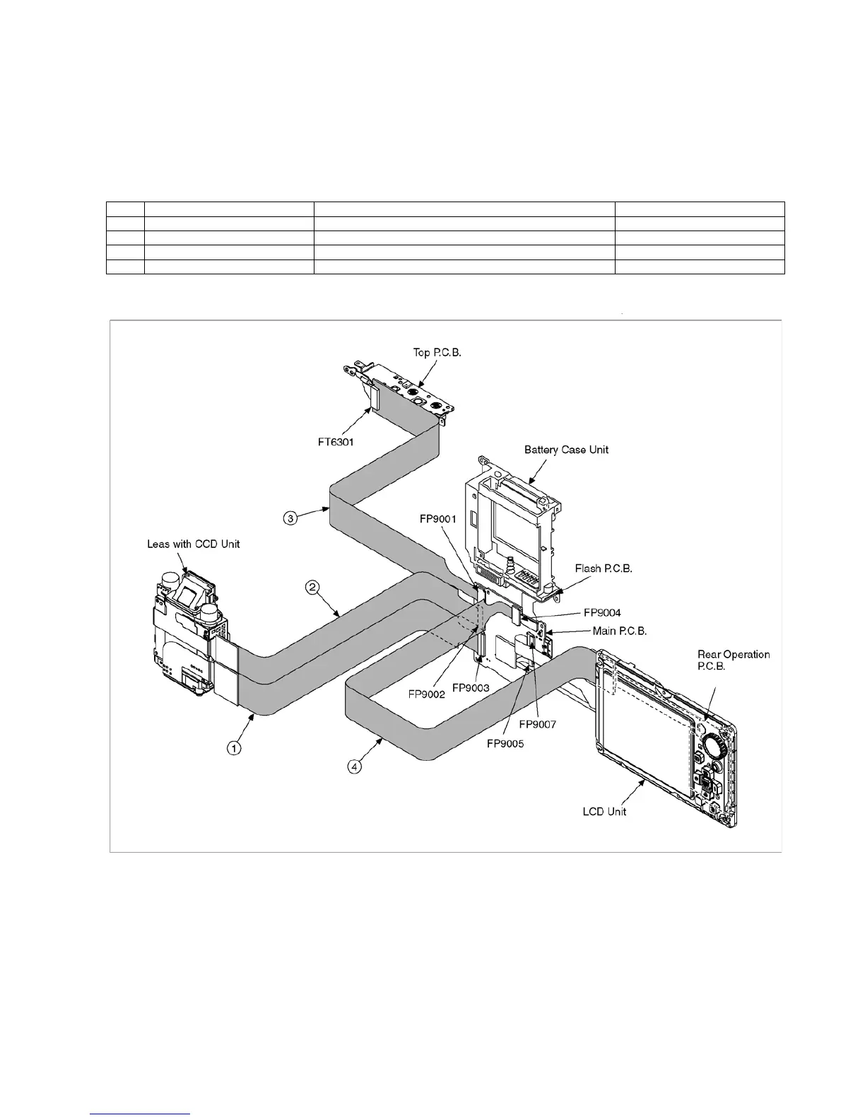
This Service Position is used for checking and replacing parts. Use the following Extension cables for servicing.
Table S1 Extension Cable List
8.3.1. Extension Cable Connections
No. Parts No. Connection Form
1 RFKZ0416 FP9003 (Main P.C.B.) - Lens with CCD unit (CCD section) 41PIN 0.3 FFC
2 RFKZ0416 FP9002 (Main P.C.B.) - Lens with CCD unit (Lens section) 41PIN 0.3 FFC
3 VFK1364 FP9001 (Main P.C.B.) - FT6301 (Top P.C.B.) 14PIN 0.5 FFC
4 VFK1174 FP9004 (Main P.C.B.) - Rear Operation P.C.B. 16PIN 0.5 FFC