38
9.3. Disassembly Procedures
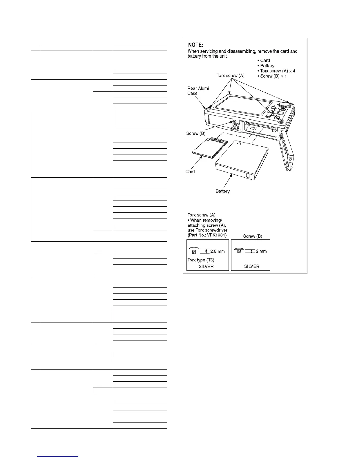
9.3.1. Removal of Rear Alumi Case
Fig. D1
No. Item Fig. Removal
1 Rear Alumi Case Fig. D1 Card
Battery
4 Screws (A)
2 Screws (B)
Rear Alumi Case
2 Top Ornament,
Shutter Button,
Power (ON/OFF) Button
Zoom Slide Lever
Fig. D2 2 Screws (C)
Top Ornament
Fig. D3 Shutter Button
Power (ON/OFF) Button
Zoom Slide Lever
3 Rear Case Unit Fig. D4 4 Screws (D)
(Tightening torque is
regretted)
2 Screws (E)
(Tightening torque is
regretted)
FP9004 (Flex)
FP9005 (Flex)
FP9007 (Flex)
Rear Case Unit
Fig. D5 Note when attaching Rear
Case Unit
4 Lens with CCD Unit Fig. D6 Peel off EMC Busterraid
Sheet
5 Screws (F)
1 Screws (G)
Screw O-ring
FP9002 (Flex)
FP9003 (Flex)
Lens Plate
Lens with CCD Unit
Fig. D7 Note when attaching Bust-
erraid Sheet
5 Main P.C.B.,
Battery Case Unit
Fig. D8 Note before removal of
Main P.C.B.
Fig. D9 1 Screws (H)
FP9001 (Flex)
Main P.C.B., Battery Case
Unit
6 Main P.C.B. Fig.D10 FP9006 (Flex)
Tab × 1
1 Screws (I)
1 Screws (J)
Tab × 1
Main P.C.B.
Fig. D11 Note after replacing Main
P. C. B.
7 Flash P.C.B. Fig. D12 1 Screws (K)
Tab × 2
FL Earth Plate
Flash P.C.B.
8 Top P.C.B. Fig. D13 1 Screws (L)
Screw O-ring
Fig. D14 5 Screws (M)
Top P.C.B.
9 Rear Operation P.C.B.
Mode Dial (1)
Fig. D15 Peel of Barrier Sheet
9 Screws (N)
Rear FPC Plate
Fig. D16 Rear Operation P.C.B.
Fig. D17 1 Screws (O)
Mode Dial Piece
Mode Dial O-ring
Mode Dial (1)
10 LCD Unit Fig. D18 4 Screws (P)
LCD Unit