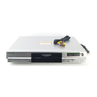
Do you have a question about the Panasonic DMR-E55P and is the answer not in the manual?
General guidelines for servicing, including part replacement and protective device installation.
Instructions for performing leakage current checks (cold and hot) to prevent shock hazards.
Cautionary note regarding fuse replacement procedures.
Information on lead-free solder distinctions and handling precautions.
Details on the power circuit, its adoption, and construction.
Procedure for forcibly ejecting a disc when the OPEN/CLOSE button fails.
Steps to take when forcible disc eject is not possible.
Information on error codes and diagnosis contents for service personnel.
Details on setting special modes like TEST Mode, Service Mode, and Forced Disc Eject.
Procedures for accessing and utilizing service modes like Error Code Display and ROM Version Display.
Procedure chart for disassembling casing and internal parts for inspection.
Diagram showing the locations of various Printed Circuit Boards (PCBs) within the unit.
Steps for removing the top case, including screw identification and lifting procedure.
Procedure for removing the Digital P.C.B., including FFC and connector disconnection.
Instructions for removing the front panel, including tab identification and connector removal.
Procedure for removing the front (R) P.C.B., including screws and front angle.
Steps for removing the DVD-RAM Drive, including screws and connector.
Instructions for removing the rear panel, including screws and locking tabs.
Procedure for removing the fan motor, including screws and fan connector.
Steps for removing the Main P.C.B., including screws and connectors.
Procedure for removing the Power P.C.B., including screws and connector.
Procedure for checking and repairing the Power P.C.B.
Procedure for checking and repairing the Main P.C.B.
Procedure for checking and repairing the Digital P.C.B.
Procedure for checking and repairing the DVD-RAM Drive.
Procedure after replacing the RAM Drive with a new one, including parameter initialization.
Procedure when the unit does not operate normally after replacing the Timer Microprocessor.
Voltage values for the Power P.C.B. measured with a DC electronic circuit tester.
Voltage values for the Main P.C.B. measured with a DC electronic circuit tester.
Voltage values for the Front (R) P.C.B. measured with a DC electronic circuit tester.
Information on P9001 connector and waveform measurements.
Block diagram illustrating the power supply system.
Block diagram illustrating the analog video processing circuits.
Block diagram illustrating the analog audio processing circuits.
Block diagram illustrating the timer functions and components.
Block diagram illustrating the digital signal processing circuits.
Pin terminal chart for digital ICs, covering TC1-18.
Diagram showing interconnections between major assemblies.
Schematic diagram of the main power supply circuit.
Schematic diagram of the sub power section (Main P.C.B. (1/5)).
Schematic diagram of the main net section (Main P.C.B. (2/5)).
Schematic diagram of the video I/O section (Main P.C.B. (3/5)).
Schematic diagram of the audio main section (Main P.C.B. (4/5)).
Schematic diagram of the timer section (Main P.C.B. (5/5)).
Schematic diagram of the glue net section (Digital P.C.B. (1/4)).
Schematic diagram of the AV encoder/RTSC section (Digital P.C.B. (2/4)).
Schematic diagram of the AV decoder/main CPU section (Digital P.C.B. (3/4)).
Schematic diagram of the audio I/O section (Digital P.C.B. (4/4)).
Schematic diagram for the Front (R) P.C.B.
Layout diagram for the Power P.C.B.
Layout diagrams for the Main P.C.B. (sections 1/4, 2/4, 3/4, 4/4).
Layout diagrams for the Digital P.C.B. (Component and Foil Sides).
Layout diagram for the Front (R) P.C.B.
Exploded views showing casing parts and mechanism sections.
Diagram showing packing and accessories included with the unit.