Pin
No.
Symbol
Description
1 Z/C Trigger input terminal.
Zero detection voltage: 0.25V
It becomes less than 3V, the mode
turns to standby.
2 F/B Bias current feedback input terminal.
Switching ON time (min.) ~ (max.)
1.5V ~ 4.5V / 0 sec. ~ 25 sec.
In standby mode
Oscillation stops:less than 0.8V
Oscillation starts: over 1.8V
3 GND GND terminal
4 Vcc Power terminal of IC.
Oscillation starting voltage: Vcc =
and over 14.5V
Oscillation stop voltage: Vcc = and
less than 9.6V
Over voltage latching voltage: Vcc =
20V
5 Drain Drain terminal for Main switching
material.
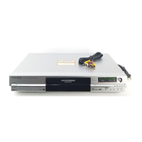
3. Startup Circuit
When power is turned on, input voltage of the Switching Transformer is supplied to IC1150 as the
startup power.
7