1 Specifications 4
2 Safety precautions
5
2.1. General guidelines
5
2.2. Caution for fuse replacement
5
3 Prevention of Electrostatic Discharge (ESD) to Electrostatic
Sensitive (ES) Devices
6
4 Precaution of Laser Diode
7
5 How to replace the Lithium Battery
8
6 Handling the Lead-free Solder
8
6.1. About lead free solder (PbF)
8
7 Each Button
9
8 New Feature
11
8.1. Quick start function(REC)
11
9 Taking out the Disc from RAM-Drive Unit when the Disc
cannot be ejected by OPEN/CLOSE button
12
9.1. Forcible Disc Eject
12
9.2. When the Forcible Disc Eject can not be done.
12
10 Service Explorer
13
11 Self-Diagnosis and Special Mode Setting
16
11.1. Self-Diagnosis Functions
16
11.2. Special Modes Setting
17
11.3. Service Modes
19
12 Assembling and Disassembling
23
12.1. Disassembly Flow Chart
23
12.2. P.C.B. Positions
23
12.3. Top Cover
24
12.4. Front Panel
24
12.5. SD Card P.C.B.
24
12.6. Digital P.C.B.
24
12.7. HDD
25
12.8. LED P.C.B. and DV Jack P.C.B.
26
12.9. DVD-RAM Drive
26
12.10. Power P.C.B.
27
12.11. Rear Panel
27
12.12. Front (L) P.C.B.
28
12.13. Main P.C.B.
28
13 Service Fixture and Tools
29
14 Service Positions
29
14.1. Checking and Repairing of Power P.C.B.
29
14.2. Checking and Repairing of Digital P.C.B.
30
14.3. Checking and Repairing of Main P.C.B.
31
14.4. Checking and Repairing of DVD-RAM Drive
33
14.5. Checking and Repairing of HDD
34
15 Caution after replacing parts
35
15.1. After replacing the RAM Drive with new one
35
15.2. When the unit does not operate normally after replacing
the Timer Microprocessor or Main P.C.B.
35
16 Standard Inspection Specifications after Making Repairs
35
17 Voltage and Waveform Chart
36
17.1. Power P.C.B.
36
17.2. Main P.C.B.
36
17.3. Tuner P.C.B.
38
17.4. LED P.C.B.
38
17.5. P9001 Connector
39
17.6. Waveform Chart
40
18 Abbreviations
41
19 Block Diagram
43
19.1. Power Supply Block Diagram
43
19.2. Analog Video Block Diagram
45
19.3. Analog Audio Block Diagram
46
19.4. Analog Timer Block Diagram
47
20 Schematic Diagram
49
20.1. Interconnection Schematic Diagram
49
20.2. Main Power Schematic Diagram
50
20.3. Sub Power Section (Main P.C.B. (1/6)) Schematic
Diagram (P)
52
20.4. Main Net Section (Main P.C.B. (2/6)) Schematic Diagram
(M)
53
20.5. Video I/O Section (Main P.C.B. (3/6)) Schematic Diagram
(V)
54
20.6. Audio Main Section (Main P.C.B. (4/6)) Schematic
Diagram (A)
56
20.7. Timer Section (Main P.C.B. (5/6)) Schematic Diagram (T)
57
20.8. UART/IR Section (Main P.C.B. (6/6)) Schematic Diagram
(U)
59
20.9. Tuner Pack Schematic Diagram
60
20.10. SD Card Schematic Diagram
61
20.11. LED/DV Jack Schematic Diagram
62
21 Print Circuit Board
63
21.1. Power P.C.B.
63
21.2. Main P.C.B.
64
21.3. Tuner P.C.B.
69
21.4. SD Card P.C.B.
70
21.5. LED P.C.B. , Front (L), DV Jack P.C.B.
71
22 Exploded Views
73
22.1. Casing Parts & Mechanism Section
73
22.2. Packing & Accessories Section
74
23 Replacement Parts List
75
CONTENTS
Page Page
3
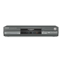
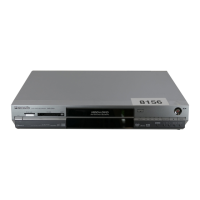
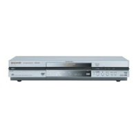
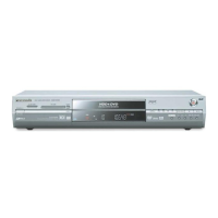
DMR-EH60PC / DMR-EH60PL / DMR-EH60GT
 Loading...