40
9.7. VHS Mechanism Unit
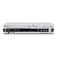
1. Disconnect 3 Connectors (P2501, P4002 and P6531).
2. Remove 3 Screws (A), Screw (B), Screw (C) and Screw
(D).
3. Lift up VHS Mechanism Unit perpendicularly so to discon-
nect Connectors (P2571 and P3001).
Note:
Pay attention to stiff connections of P2571 and P3001,
when removing VHS Mechanism Unit.
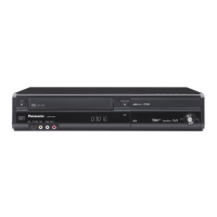
9.7.1. Caution for attaching VHS Mecha-
nism Unit
1. Because Position SW should be set to "Eject Position",
refer to fig.(A) and set the position switch so that the boss
and arrow mark come on a straight line.
2. Attach VHS Mechanism Unit so that Boss of Position SW
is put into long hole of Main Cam Gear, refer to Fig. (B).
 Loading...