Do you have a question about the Panasonic DMR-EZ49VEG and is the answer not in the manual?
Main product category and title of the service manual.
Provides essential safety rules and guidelines for servicing the unit.
Details precautions to protect electrostatic sensitive devices from static discharge during handling.
Safety measures related to the laser diode assembly and its operation.
Important cautions for service personnel related to legal constraints and solder types.
Guides on accessing service information and warnings for DivX functionality.
Procedure to check the continuity of the micro fuse using a tester.
Instructions for verifying the normal and abnormal operation of USB devices.
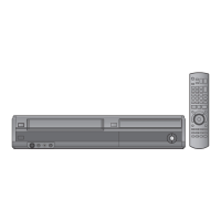
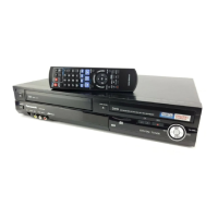
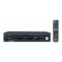
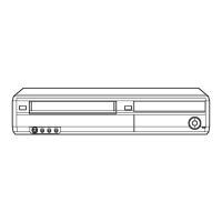
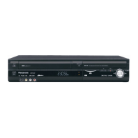
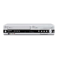
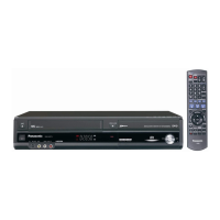
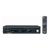
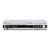
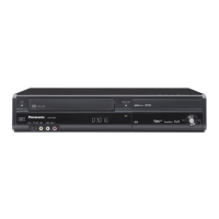
Identifies and describes the function of all controls and indicators on the unit's front, rear, and display.
Provides methods for forcibly ejecting a DVD disc when the standard method fails.
Outlines two methods for manually removing a VHS cassette tape due to malfunctions.
Describes DVD self-diagnosis features and how to set special operational modes.
Details specific settings for various DVD special modes like TEST, Rating, and Aging.
A quick reference for DVD service modes, including release items and key operations.
Information on VHS self-diagnosis and how to access special modes.
Explains the VHS self-diagnosis history memory and procedures for clearing it.
A visual guide detailing the sequence for disassembling the unit's internal components.
Illustrates the physical locations of various PCBs within the unit for easy identification.
Provides step-by-step instructions for removing the top case and front panel.
Detailed steps for detaching the Front Jack and FL Drive printed circuit boards.
Instructions for disconnecting and attaching the VHS mechanism unit, including cautions.
Guidance on removing and replacing the RAM/Digital P.C.B. module, including notes on alignment.
Steps for detaching the SD/USB P.C.B. and its associated angle bracket.
Instructions for disassembling the rear panel and removing the fan motor assembly.
Procedures for detaching the HDMI P.C.B. and Digital IF P.C.B.
Step-by-step instructions for removing the Backend and Main P.C.B.s.
Outlines service positions and procedures for checking and repairing the Digital IF P.C.B.
Important notices and procedures to follow after replacing specific components like the RAM/Digital P.C.B.
Specifies the standard inspection requirements for DVD functions after repairs.
Critical safety guidelines and notation explanations for understanding schematic diagrams.
Lists standard voltage values measured at various pins of the VHS Main P.C.B.
Provides voltage measurements for pins on the SD_USB and Digital IF P.C.B.s.
Lists voltage values for the FL Drive P.C.B. pins.
Diagram illustrating the power supply circuit and its components.
Shows the regulator circuits and their connections on the Main P.C.B.
Illustrates the signal flow for analog video input and output, Part 1.
Continues the illustration of analog video signal paths and processing, Part 2.
Illustrates the signal flow and components for analog audio input/output, Part 1.
Completes the diagram of analog audio signal paths and processing, Part 2.
Shows the electrical connections between major PCBs and external connectors, Part 1.
Continues the diagram illustrating electrical connections between PCBs, Part 2.
Shows the placement of components on the VHS Main P.C.B., component side.
Illustrates the trace layout on the VHS Main P.C.B., foil side.
Displays the component placement and trace layout for the Front Jack P.C.B.
Shows the arrangement of components on the SD_USB P.C.B., component side.
Illustrates the trace layout on the SD_USB P.C.B., foil side.
Displays component placement and trace layout for the HDMI P.C.B.
Shows the component layout on the Digital IF P.C.B., component side.
Illustrates the trace layout on the Digital IF P.C.B., foil side.
Shows the component placement on the FL Drive P.C.B., component side.
Illustrates the trace layout on the FL Drive P.C.B., foil side.
A list of abbreviations used in the DVD sections of the manual.
A list of abbreviations specific to the VHS sections of the manual.
Exploded view of the unit's frame and casing components, Part 1.
Exploded view of the unit's frame and casing components, Part 2.
Exploded view illustrating the internal mechanism components of the unit.
Exploded view showing the packaging materials and accessories included with the unit.
| Type | DVD Recorder |
|---|---|
| Recording Format | DVD-RAM, DVD-R, DVD-RW, DVD+R, DVD+RW |
| Video Format | PAL |
| Progressive Scan | Yes |
| Video Recording Format | MPEG-2 |
| Connectivity | HDMI, USB, Component Video, Composite Video, S-Video |
| Dimensions (W x H x D) | 430 x 59 x 286 mm |
| Video Output | HDMI, Composite, Component |
| Playback Media | DVD, DVD-RAM, DVD-R, DVD-RW, DVD+R, DVD+RW, CD, CD-R, CD-RW |
| Video Playback Format | MPEG-2, DivX |
| Audio Recording Format | Dolby Digital |
| Audio Playback Format | Dolby Digital, PCM, MP3 |
| TV Tuner | Yes, Digital and Analogue |