47
6.2.2 Grid Connection
The connection procedure will vary depending on the grid configuration.
CAUTION!
The installer is responsible for providing overcurrent protection.
To reduce the risk of fire, only connect to a circuit provided with
overcurrent protection in accordance with the National
Electrical Code, ANSI/NFPA 70.
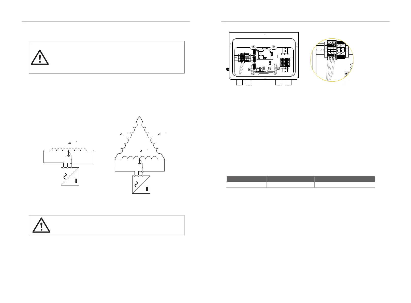
L1
L2
N
240V/120V Split Phase AC Grid
240V 180
L1
L2
N
240V/120V Stinger AC Grid
240V 180
240V 180 240V 180
• Public grid configuration allowed:
Ÿ Grid terminal connection on the side of inverter
CAUTION!
DANGER — HIGH VOLTAGE!
For the specific requirement of power cable, please refer to section 6.1 “Overview
of All Electrical Wiring Methods”.
46
The AC circuit breaker (not included in the EVERVOLT Hybrid inverter) is required
to protect each AC line (L1 and L2) of the inverter. The circuit breaker should be
able to handle the rated maximum output voltage and current of the inverter.
Ÿ AC circuit breaker requirements
A: L1 terminal B: L2 terminal C: N terminal
Inverter model Source
EVHB-I7
Eaton, BR series, BR240
Description
Purchase separately
The following diagram provides an overview of the compatible grid configurations
of which voltage limit, frequency limit and conductors have to be connected to the
inverter to comply with the grid configuration.
Refer to the table below to determine the specific circuit breaker in order to avoid
potential fire hazards. The AC circuit breaker selection and installation must
follow the National Electrical Code(NEC), ANSI/NFPA 70 or local electrical codes.
A
B
C
Electrical Connection Electrical Connection
BAT-
BAT+
Neutral
HOT L2
HOT L1
PV3-
PV3+
PV2-
PV2+
PV1-
PV1+
BAT