11
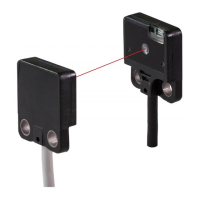
Thru-beam type: EX-13S□, parallel deviation diagram (typical)
100 50 0 50 100
800
0
600
400
200
(
L9
)
(
ℓ9
)
Sensing distance L (mm)
CenterLeft
Right
Operating point ℓ(mm)
<Installation interval for EX-13S□
>
In case using at sensing distance (L9)
500mm, the operation point (ℓ9) is approx.
37.1mm according to diagram above.
The installation interval is
Approx. 37.1mm × 2 = approx. 74.2mm
Thus, install approx.74.2 or more away.
Emitter Receiver
EX-13S□: approx. 74.2mm or more
500mm
EX-13S□: approx. 74.2mm or more
Thru-beam type: EX-13SE□, parallel deviation diagram (typical)
(
L10
)
(
ℓ10
)
100 50 0 50 100
800
0
600
400
200
CenterLeft
Right
Operating point ℓ(mm)
Sensing distance L (mm)
<Installation interval for EX-13SE□
>
In case using at sensing distance (L10)
500mm, the operation point (ℓ10) is approx.
29.2mm according to diagram above.
The installation interval is
Approx. 29.2mm × 2 = approx. 58.4mm
Thus, install approx.58.4 or more away.
EX-13SE□: approx. 58.4mm or more
500mm
EX-13SE□: approx. 58.4mm or more
Emitter Receiver
info@digiparts.ch
www.digiparts.ch
Ihr Schweizer Industriepartner

 Loading...