Do you have a question about the Panasonic EYFR02 and is the answer not in the manual?
| Brand | Panasonic |
|---|---|
| Model | EYFR02 |
| Category | Measuring Instruments |
| Language | English |
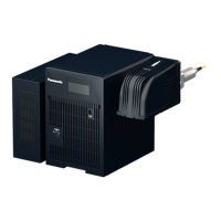
Connector for input/output signals, including reset and relay outputs.
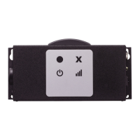
Audible alert device for status notifications.
Adjusts the audible alert volume level.
Indicates a successful fastening operation.
Transmits and receives wireless signals for communication.
Indicates a failed fastening operation.
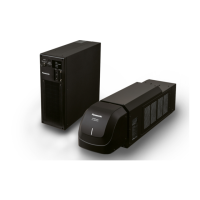
Provisions for securely mounting the unit.
Displays the strength of the wireless signal.
Shows the operational status of the unit's power.
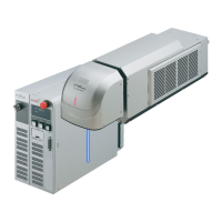
Secures the mode switching key in place.
9-pin D-sub connector for data or control.
Turns the unit's power on or off.
Port for connecting the power cord.
Keys used to switch operational modes.
Cable used to supply electrical power to the unit.
Guidance on effective use and understanding of the operating manual.
Essential safety information, warnings, and cautions for safe operation.
Instructions for obtaining the necessary Device Programmer application software.
Details on the computer hardware and OS needed for the software.
Step-by-step guide for installing the Device Programmer application.
Process for connecting and setting up the assembly qualifier via software.
Overview of functions available in the File menu of the software.
Functionality related to selecting and loading products in the software.
Configuration options for COM port settings in the software.
Accessing software version information.
Physical mounting instructions for the assembly qualifier unit.
Procedure to pair a tool with the assembly qualifier for monitoring.
Explanation of the different indicators and their operational states.
Adjusting the audible alert volume using the volume switch.
How to use the software to monitor tool fastening during operation.
Steps to properly shut down the assembly qualifier after use.
Detailed pin configuration and description for the I/O connector.
Diagram and pin assignments for the 5-pin connector.
Illustrates how to connect the qualifier to external devices.
Specifications related to wireless transmission and reception.
Regulatory compliance information and statements.
List of available wireless communication channels and their frequencies.