Specifications
FP0 A/D Converter Unit
7 − 5
7.1 Specifications
• (
∗
3) Setting value switch for the number of input channels
• (
∗
4) The control unit loads two channels’ worth of data at each control
unit scan.
In other words, if the switch for the number of input channels is
set to eight channels, the control unit data is updated once every
four scans.
• (
∗
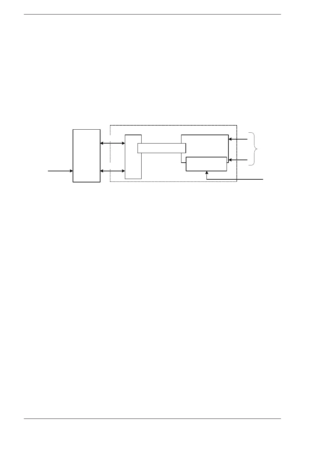
5) Refer to the schematic diagram of insulation methods below.
Analog input circuit
FP0
control unit
I/F
Photocoupler insulation
DC/DC
converter insulation
Bus
+5V
24V DC
A/D converter unit
24V DC
ch0 to ch7
• (
∗
6) The contact numbers change depending on the expansion
position (these values are for the case when the unit is installed
in the closest position to the control unit).
For details refer to page 6 − 3, “6.1 I/O Number of A/D Converter
Unit”.