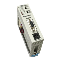
FP2−CCU
RS232C Port Wiring
4 − 6
4.2 Wiring between RS232C Ports
4.2.2 Connections with Operation Display Panel
An RS232C cable (Product No. AFB85813) is available for making connections to an
operation display panel that has a D−sub 25−pin connector.
AFB85813
(Crossing cable: 9−pin external — 25−pin external)
1
6
25
13
3000
100
/118.11
3.937
1
M2.6 screws
Dimension
2
M2.6 screws
(unit: mm/in.)
Wiring diagram
D−sub 9−pin external D−sub 25−pin external
Pin No.
PLC side
Display panel side
Signal name
(Mnemonic)
1
2
Pin No.
FG
SD
RD
RS
RI
SG
CD
ER
1
2
3
4
5
6
7
8
9
CS
1
2
3
4
5
6
7
8
20
Signal name
(Mnemonic)
FG
SD
RD
RS
DR
SG
CD
ER
CS
− The “RS” and “ER” signals of the Computer Communication Unit side
are constantly on.
− The input to the “CS” and “CD” terminals of the Computer Communica-
tion Unit side are invalid.
Tip



 To Next Page

