1-10-17
11
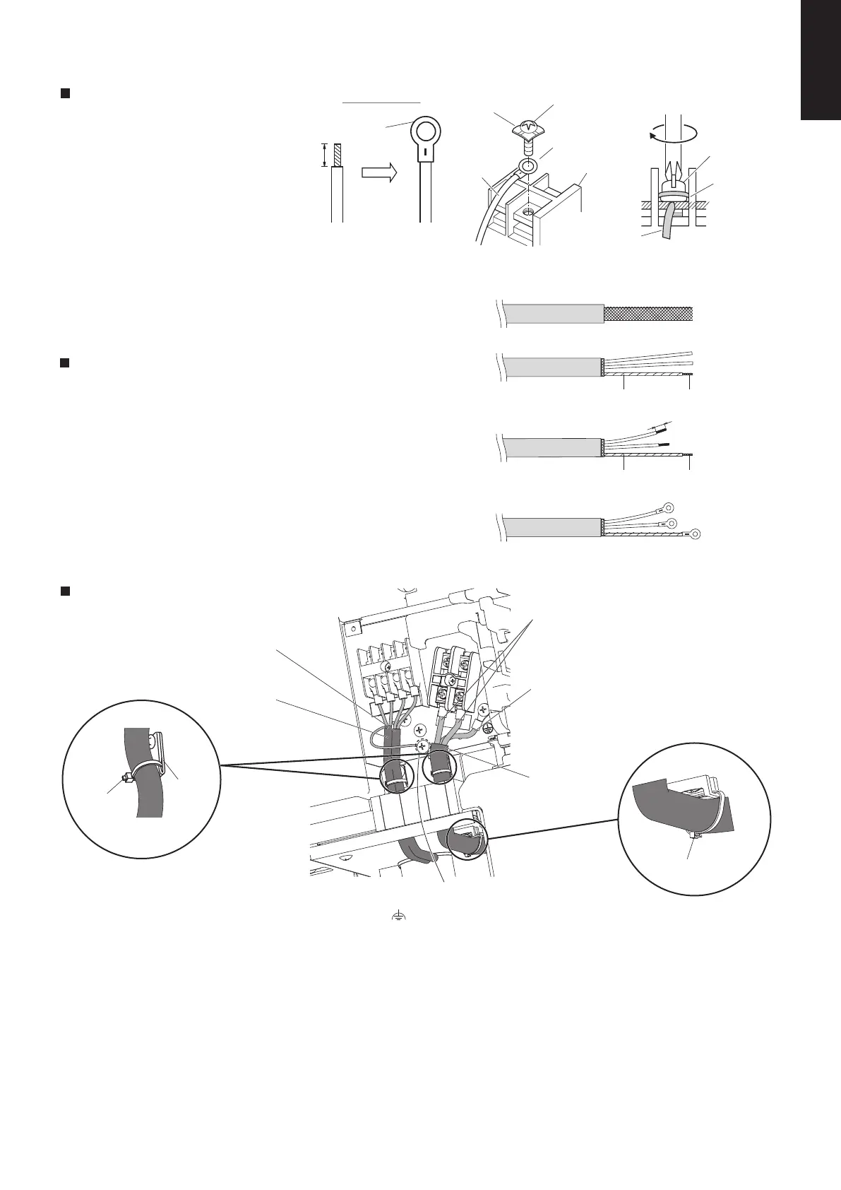
Wiring samples
Type U2
Use this screw when connecting the shield
for the Inter-unit control wiring to ground.
(
: Functional earthing)
*1 Fasten tightly.
Earth Wiring:
Make the earth wiring 25 - 30 mm longer than power
cable.
Power Supply
Power cable
Inter-unit Control
Wiring
Clamper
*
1
(supplied)
Clamper
*
1
(supplied)
Clamping
Clip
Remote Control
Wiring
Insulation tape
8 mm
Insulation tape
Shield mesh
Shield mesh
Fig. 1-10-8
Fig. 1-10-9
Fig. 1-10-10
Fig. 1-10-11
Examples of shield wires
(1) Remove cable coat not to scratch braided shield. (Fig. 1-10-8)
(2) Unbraid the braided shield carefully and twist the
unbraided shield wires tightly together. Insulate the shield
wires by covering them with an insulation tube or wrapping
insulation tape around them. (Fig. 1-10-9)
(3) Remove coat of signal wire. (Fig. 1-10-10)
(4) Attach ring pressure terminals to the signal wires and the
shield wires insulated in Step (2). (Fig. 1-10-11)
Stranded wire
Ring
pressure
terminal
Screw and
Special washer
Ring
pressure
terminal
Terminal board
Ring pressure
terminal
Screw
Special
washer
Wire
Wire
Strip 10 mm
Fig. 1-10-6
Fig. 1-10-7
How to connect wiring to the terminal
For stranded wiring
(1)
then strip the insulation to expose
the stranded wiring about 10 mm and
tightly twist the wire ends. (Fig. 1-10-6)
(2)
remove the terminal screw(s) on the
terminal board.
(3)
pliers, securely clamp each stripped
wire end with a ring pressure terminal.
(4)
Cut the wire end with cutting pliers,
Using a Phillips head screwdriver,
Using a ring connector fastener or
Place the ring pressure terminal,
and replace and tighten the removed
terminal screw using a screwdriver.
(Fig. 1-10-7)
SM830266-00_大洋州向けR32シングルTD&SM.indb 17 18/03/29 10:20:01

 Loading...