22
2-10
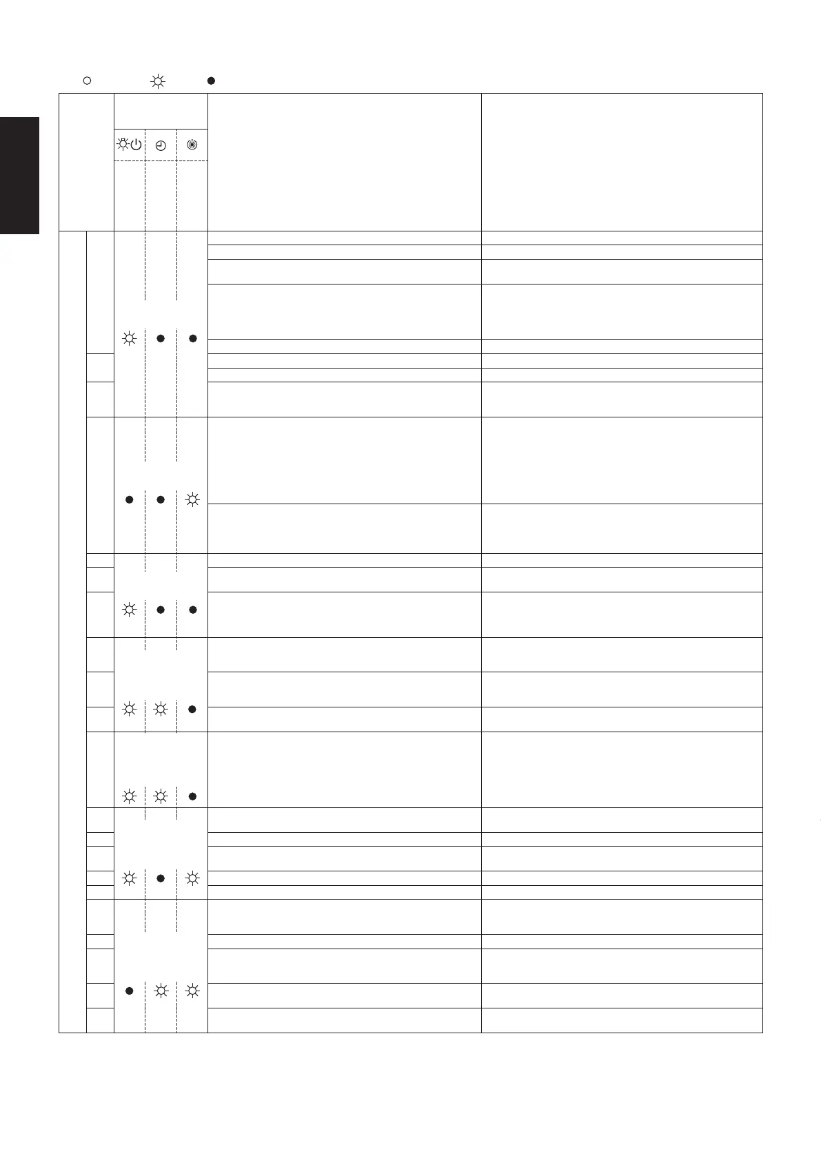
2-10. Table of Self-Diagnostic Functions and Corrections
ON: Blinking: OFF:
Abnormal
display
Wireless remote
controller
receiver display
Alarm contents Error location
Operation
Timer
Standby
Remote controller • Indoor Unit
E01
Operating lamp
blinking
• Faulty remote controller • Replace the remote controller
•
Disconnection / Contact failure of remote controller wiring
• Correct the remote controller wiring
• CHK (check) pins on the indoor unit control PCB are
short circuited
• Remove the short
• In the case of non-group control : Power supply OFF of
outdoor unit
Disconnection / Contact failure of inter-unit wiring
• In the case of group control : Automatic address
operation was not carried out
• Execute auto address setting
• Faulty setting of EEPROM (IC010) on indoor unit • Replace the indoor unit EEPROM
E02
• Faulty remote controller • Replace the remote controller
• Wrong wiring of remote controller • Correct the remote controller wiring
E03
• Error in indoor unit receiving signal from remote
controller (central)
• Check the indoor unit control PCB
• Check the remote controller wiring
• Check the inter-unit control wiring
E04
Standby lamp
blinking
• Disconnection / Contact failure of inter-unit wiring
• Faulty indoor unit control PCB
• Faulty outdoor unit control PCB
• Communication circuit fuse (F302) on indoor unit control
PCB opened
• Check the electrical connection of inter-unit control wiring
• Replace the indoor unit control PCB
• Replace the outdoor unit control PCB
• Check the electrical connection of fuse (F302) on indoor
unit control PCB
In the case of the fuse opened on an indoor unit control
PCB, after correcting wiring connection, it substitutes an
EMG plug for OC plug
• Fuse on outdoor unit control PCB opened
Since failure of an outdoor fan motor is considered as a
cause, both outdoor unit control PCB and outdoor unit
fan motor are exchanged simultaneously
• In the case of the fuse opened on an outdoor unit control
PCB, replace both outdoor unit control PCB (CR/HIC) and
outdoor unit fan motor simultaneously
E08
Operating lamp
blinking
• Duplication of indoor unit address setting • Indoor unit address re-setting
E09
• Error because of more than one remote controller setting
to main
• Correct the setting
E18
• Disconnection of wiring between main unit and additional
units
• Contact failure of wiring
• Faulty indoor unit control PCB (main or addition)
• Correct the wiring connection
• Replace the wiring
• Replace the indoor unit control PCB
F01
Operating
and timer
lamp blinking
alternately
• Indoor heat exchanger temperature sensor (E1) trouble
• Check the indoor unit heat exchanger temperature sensor
(E1)
• Check the indoor unit control PCB
F02 • Indoor heat exchanger temperature sensor (E2) trouble
• Check the indoor unit heat exchanger temperature sensor
(E2)
• Check the indoor unit control PCB
F10 • Indoor air temperature sensor (TA) trouble
• Check the indoor unit air temperature sensor (TA)
• Check the indoor unit control PCB
F29
Operating
and timer
lamp blinking
simultaneously
• Indoor unit EEPROM trouble
• Check the indoor unit EEPROM
• Check the indoor unit control PCB
L02
Operating
and standby
lamps blinking
simultaneously
• Setting error, indoor / outdoor unit type / model miss-
matched
• Address re-setting after correcting the combination of units
L03 • Duplication of main indoor unit address in group control • Correct the group (main and addition)
L07
• Group control wiring is connected to individual control
indoor unit
• Correct the indoor unit address
L08 • Indoor unit address is not set • Correct the indoor unit address
L09 • Indoor unit capacity is not set • Correct the capacity setting of indoor units
P01
Timer and
standby
lamp blinking
alternately
• Indoor unit fan motor locked
• Indoor unit fan motor layer short
• Contact failure in thermostat protector circuit
• Remove the cause
• Replace the fan motor
• Correct the wiring
P09 • Faulty wiring connections of (ceiling) indoor unit panel • Correct the wiring connection
P10
• Faulty drain pump
• Drainage failure
• Contact failure of oat switch wiring
• Repair / Replace
• Correct
• Correct the wiring
P11
• Faulty drain pump
• Drain pump locked
• Repair / Replace
• Remove the cause
P12
• Indoor unit fan motor locked
• Faulty wiring connections of indoor unit fan motor
• Remove the cause
• Correct the wiring
01_301769_2WAY_eng.indb 37 2018/3/20 9:15:16
ON: Blinking: OFF:
Abnormal
display
Wireless remote
controller
receiver display
Alarm contents Error location
Operation
Timer
Standby
Outdoor Unit
E06
Standby lamp
blinking
• Disconnection / Contact failure of inter-unit wiring
• Disconnection of inter-unit wiring
• Communication circuit fuse (F302) on indoor unit control
PCB opened
• Correct the inter-unit control wiring
Check the electrical connection of fuse (F302) on indoor
unit control PCB
In the case of the fuse opened on an indoor unit control
PCB, after correcting wiring connection, it substitutes an
EMG plug for OC plug
• Indoor unit control PCB address settings error • Indoor unit address re-setting
E12
Operating lamp
blinking
• Auto address setting start is prohibited • Check the inter-unit control wiring
E14 • Duplication of main unit in group control
• Check the inter-unit control wiring
• Check the indoor unit combination
E15
Standby lamp
blinking
Automatic
address
alarm
• The total capacity of indoor units are too
low
• Check the inter-unit control wiring
• Check the indoor and outdoor unit control PCBE16
• The total capacity of indoor units are too
high
• The number of indoor units is two or more
E20 • No indoor unit connected
E24 • Outdoor unit communication error • Check the outdoor unit control PCB
E29 • Outdoor unit communication error • Check the outdoor unit control PCB
F04
Operating
and timer
lamp blinking
alternately
• Compressor discharge temperature sensor (TD) trouble
• Check the compressor discharge temperature sensor (TD)
• Check the outdoor unit control PCB
F06
• Outdoor heat exchanger temperature sensor (C1)
trouble
• Check the outdoor unit heat exchanger temperature
sensor (C1)
• Check the outdoor unit control PCB
F07
• Outdoor heat exchanger temperature sensor (C2)
trouble
• Check the outdoor unit heat exchanger temperature
sensor (C2)
• Check the outdoor unit control PCB
F08 • Outdoor air temperature sensor (TO) trouble
• Check the outdoor air temperature sensor (TO)
• Check the outdoor unit control PCB
F12 • Compressor suction temperature sensor (TS) trouble
• Check the compressor suction temperature sensor (TS)
• Check the outdoor unit control PCB
F31
Operating
and timer
lamp blinking
alternately
• Outdoor unit EEPROM trouble
• Check the outdoor unit EEPROM
• Check the outdoor unit control PCB
H01
Timer lamp
blinking
• Primary (input) overcurrent detected
• Check the refrigerant cycle (abnormal overload operation)
• Check the outdoor unit control PCB
• Check the power supply
H02 • PAM trouble
• Check the outdoor unit control PCB
• Compressor locked
• Check the power supply
H03 • Primary current CT sensor failure • Check the outdoor unit control PCB
H31
• HIC trouble
• DC voltage not detected
• Check the outdoor unit control PCB
• Check the HIC
• Compressor locked
• Valve blockage
L04
Operating
and standby
lamps blinking
simultaneously
• Duplication of outdoor unit address • Check the inter-unit control wiring
L10 • Outdoor unit capacity is not set or setting error
• Replace the outdoor unit EEPROM
• Capacity value re-setting
L13
• Indoor unit type setting error
• Type of indoor/outdoor units is different
• Replace the indoor unit EEPROM
• Check the outdoor unit control PCB
• Check the type of IU and OU, and re-set address
L18 • 4-way valve locked trouble / operation failure
• Check the 4-way valve
• Check the 4-way valve wiring
• Check the outdoor unit control PCB
P03
Operating
and standby
lamp blinking
alternately
• Compressor discharge temperature trouble
• Check the refrigerant cycle (gas leak)
• Trouble with the electronic expansion valve
• Check the discharge temperature sensor (TD)
P04 • Compressor discharge pressure trouble
• Check the refrigerant cycle
• Valve blockage
• Heat exchanger obstruction
P05
• Open phase detected
• AC power supply trouble
• Check the power supply
• Check the reactor wiring
• Check the outdoor unit control PCB
• Check the compressor wiring
01_301769_2WAY_eng.indb 38 2018/3/20 9:15:16
SM830266-00_大洋州向けR32シングルTD&SM.indb 10 18/03/29 11:58:30
 Loading...