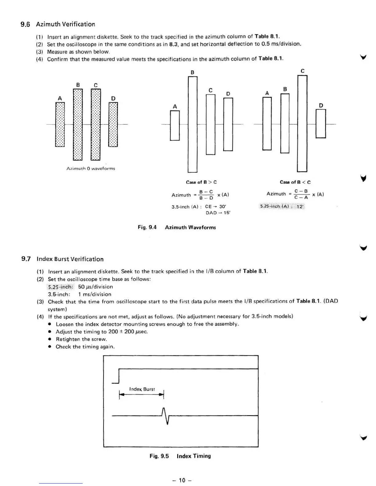
9.6
Azimuth
Verification
(1) Insert an alignment d
is
kette
. Seek to the track specified
in
the azimuth column of Table B.l .
(2) Set the
osc
ill
oscope
in
the
same conditions
as
in
B.3, and
se
t horizontal deflection to 0,5 ms/division.
(3) Measu
re
as
shown below.
(4) Confirm
that
the measured value meets
the
specifications
in
th
e azimuth column of Table B.l ,
B
c
B
C
c
o
A
B
A
0
A
:!
A
)!,
m u(h 0 wavefo
rm
$
CaseofB
> C
C_ofB
< C
o
B- C
Azimuth
· B _ D >(
(AI
C- B
Azimurh
,.
---
x (
AI
C- A
9.7
Index
Bu
rs
t Verification
3.5·inch
IAI
:
CE
-
30'
DAD
-
15
'
Fig
. 9.4 Azimuth Waveform,
S.2S·inch
1M
:
12'
(
1)
Insert an alignment d
isk
ett
e.
Seek to the track specified in the liB column of Table B.l .
(2) Set the
oscilloscope time base as follows:
S.2S
·i
nch:
50
ps/
di
vision
3.5
-i
nch: 1 ms/division
(3) Check
that
the
ti
me
fr
om
oscilloscope start to the first data pul
se
meets the 1/8 specif
ic
at
io
ns of Table 8.1. (DAD
system)
(4)
It
the
specif
ica
tions are
not
met, adjust
as
follo
ws.
(No adjustment necessary for 3.5·inch models)
•
Loosen
the
index dete
cto
r mounting screws enough
to
free the assembly.
• Adjust
the
timing
to
200
±
200
psec.
•
R
et
ighten
the
screw.
• Check
the
timing again.
I" Indell. Burst
..
/
v
Fig. 9.5 Index Timing
- 10 -
 Loading...