•
•
•
•
•
9.8 Track
00
Sensor Adjustment
(1) Set the oscilloscope
as
follows.
Set
h
orizontal
deflection t o 1 mYdivision.
CH1
EXT
S.2S-in
ch
TP-8
Tp·12
3. 5·inch
zp
SP
(21
Step
between
specified tracks
at
in
the
FLAG
0 item
ofTable
8.1 (Turn
the
seek
de
lay switch
on
the
exercis
er
to
adjust 12
ms
seek.)
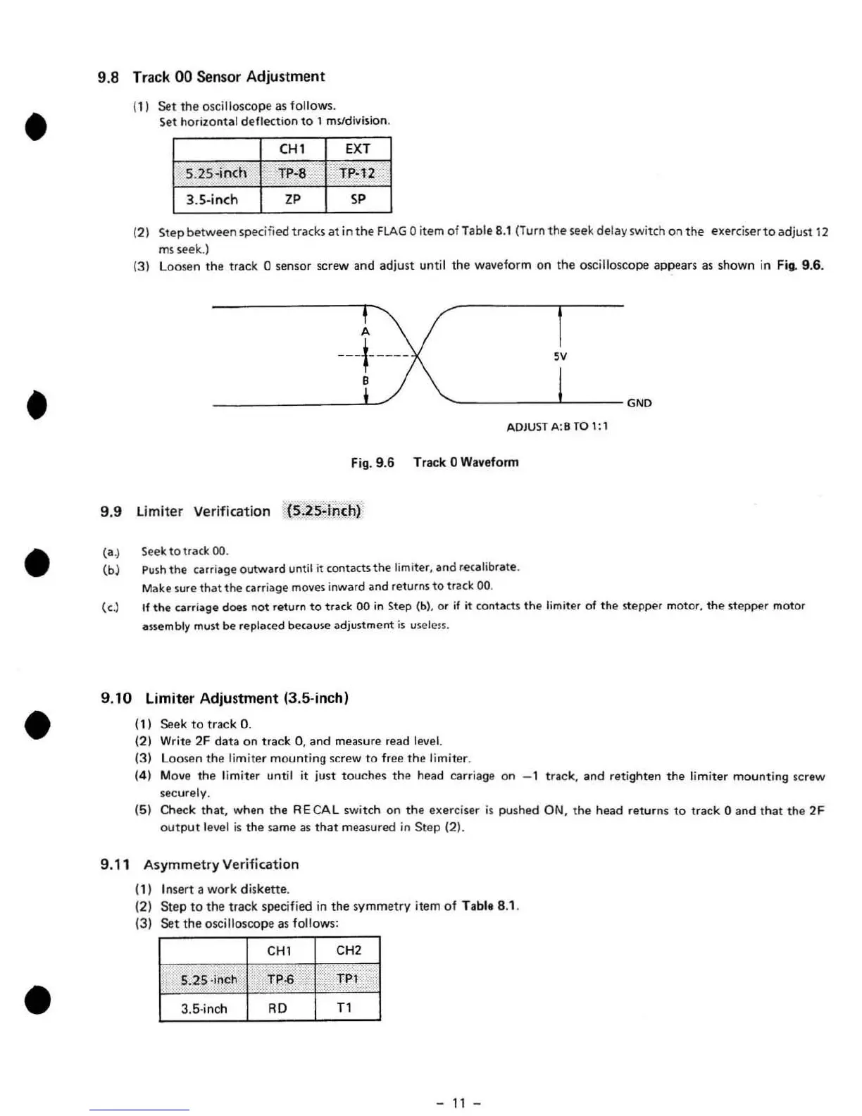
(3)
loo
sen the track 0 sensor screw and adjust until the waveform on the oscilloscope appears as shown in
Fig
. 9.6.
A
--
+
----
sv
'-------
--~------G
ND
ADJUST A:B
TO
1:1
Fig
. 9.6 Track 0 Waveform
g,g
limiter
Verification
(S
;
)S:inchr
(a
.)
(b)
Seek
to
track
00
.
Push
the
carriage
outwllrd
until
it
contacts
the
lim
i
ter
, and recOlIlibrate.
Make sure
that
the
carriage moves inward and returns
to
track 00.
{el
If
the carriage does not return
to
track
00
in
Step
(b),
or if
it
contacts
the
limiter of the stepper motor.
the
stepper motor
assembly must be replated because adjustment
is
u§eless
.
9.
10
limiter
Adjustment (3.5-inchl
(11
Seek
to
track O.
(21
Write 2F
data
on
track
0,
and
measure read level.
(31
Loosen
the
limiter
mounting
screw
to
free
the
limiter.
141
Move
the
limiter until it just
touch
es
the
head carriage
on
- 1 track.
and
retighten
the
limiter
mounting
screw
securely.
(5) Check
th
at, when the A E
CA
L switch
on
the
exerciser
is
pushed ON,
the
head returns
to
track 0 and
that
the
2F
output
level
is
the
same
as
that
measured in
Step
(21.
9.11 Asymmetry Verification
(1) I nsert a work diskette.
(2)
Step
to
the track specified in
the
symmet
ry
item
of
T
ab
le 8.1.
(3)
Set
the
oscilloscope
as
follows:
CH
1
CH2
S.
2S
-inch
TP-6
..
II
TP'
/
3.5
·inch
RD
T1
-
11
-
 Loading...