11.8
Stepper
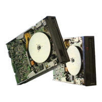
Motor Assembly Removal
and
Installation
(S
ee
Fig
.
11
.8)
(1)
Remove
the
insulating
paper
and
shield
plate
.
(2)
Remove
the
track 00 sensor as described
in
11.3.
(3
) Remove
the
two
(M2
x
4)
actuator
screws
that
fasten
the
actuato
r
to
the
carriage arm
assembly.
(4) Remove
the
two
(M3
x
6)
stepper
motor
assembly
moun
ting screws
an
d
then
the
stepper
·motor.
(5)
Reverse
the
above
procedure to reinstall.
(6)
After reinstallation, perform limiter check as
in
9.
10
an
d radial
alignment
adju
stment
as
in
9.5.
(7)
Adjust
th
e track 00 sensor according to
the
ins
tru
ction in 9.8.
Fii- " .8
Stepper
Motor Assembly Removal
- 16 -
11
.9 Carriage Arm Assembly Removal
and
Insta
ll
atio
n (See Fig.11.
9)
(1) Remove
the
printed
circuit board as described
in
11
.1.
(2)
Remove
the
insulating
paper
and
shield pl
ate
.
(3)
Remove
the
track 00 assembly as descrj
bed
in
11.3.
(4)
Remove
the
stepper
motor
assembly
as
descri
bed
in
11
.8.
(5)
Remove
the
two
guide rod clamp
mounting
screws.
(6)
Re
move
the
carriage arm assemb
ly,
guide
rod
damp
, and
guide
rod.
(7)
Pul
lout
the
guide rod from
the
ca
rri
age
arm
assemb
ly
.
(8) Reverse
the
above
procedure
to
reins
ta
ll.
(9)
After replacement, perform limiter
adjustment
as described
in
9.10,
tr
ack 00
sensor
adjustment
as described in 9.8, and
radial ali
gnment
adju
stment
as described in
9.5.
Gu ~e
R
.
'
~C-
__
___
.
__
~'
Fig. " .9 Carriage
Arm
Anembly
Removal
 Loading...