Do you have a question about the Panasonic KX-FP701ME and is the answer not in the manual?
Safety guidelines for service technicians, including AC power handling and static prevention.
Precautions related to AC power connections and grounding for safety.
Warnings about moving parts and live electrical sections during servicing.
Precautions regarding static electricity damage to electronic components.
Information and cautions regarding the use of lead-free solder in repairs.
Instructions for securely discarding printed circuit boards.
Procedure for performing an insulation resistance test for shock hazard prevention.
Warnings and precautions for handling and replacing the lithium battery.
Lists error messages displayed by the unit in different languages.
Lists optional accessories available for the unit.
Details of the fax machine's general capabilities and copier functions.
Illustrates the electrical connections between different boards and components.
Outlines the function of each major IC on the digital board.
Describes the control section's block diagram and memory map.
Visual representation of the memory organization and address allocation.
Details the functions and pin descriptions of the ASIC (IC1).
Details the function and address range of the Flash Memory (IC6).
Details the function and address range of the Dynamic RAM (IC4).
Explains the reset circuit operation and its relation to the watchdog timer.
Describes the Real-Time Clock backup circuit operation using a lithium battery.
Explains the circuit that monitors thermal head temperature for print quality.
Details the flow of image data during copy, transmission, and reception.
Visual representation of the facsimile section's data flow.
Explains the thermal head's function, circuit operation, and driver ICs.
Details the scanning block's components and signal processing for image acquisition.
Explains the RX stepping motor's function, drive circuit, and modes.
Explains the TX stepping motor's function, drive circuit, and modes.
Lists and describes the function and location of various sensors and switches.
Explains the modem's function and overview of facsimile communication procedures.
Details the modem's circuit operation for facsimile transmission and reception.
Explains the NCU's function, relay circuits, and dial/bell circuits.
Describes the line amplifier and side tone circuit operation.
Explains the Caller ID circuit operation using FSK modulation.
Explains the Caller ID circuit operation using DTMF signals.
Details the ITS and monitor functions, including telephone monitor.
Explains the circuit controlling conversation over the handset.
Describes circuits monitoring various tones like DTMF, alarm, and bell.
Details the operation board components like LCD, keys, and LEDs, and their control.
Explains the LCD section's operation and display modes.
Describes the power supply board's switching regulator method and block diagram.
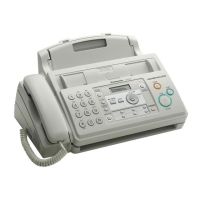
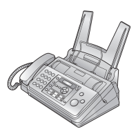
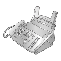
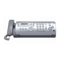
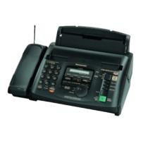
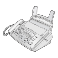
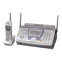
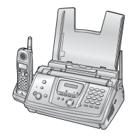
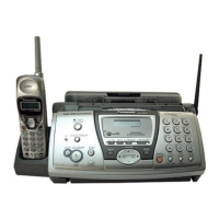
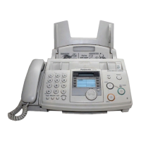
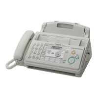
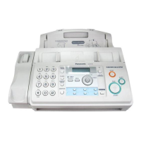
Provides an overview of the unit's external controls and components.
Identifies and explains the functions of each button on the control panel.
Specifies the required space and environmental conditions for unit installation.
Guides on connecting the telephone line cord, power cord, and other devices.
Step-by-step instructions for installing the ink film correctly.
Instructions for correctly installing the paper tray into the unit.
Instructions for inserting the paper support into its slot.
Details on how to install recording paper, including document requirements.
Instructions on how to program and set a user logo for page printing.
Explains how to select DTMF signal tones for testing.
A table mapping dial keypad codes to button names for various functions.
Instructions and examples for printing test patterns to check print quality.
Details the two categories of programming: User Mode and Service Mode.
A table detailing service codes, functions, set values, and defaults.
Specifies the behavior of memory clearing in different service modes.
Provides an example of a printed list for user mode settings.
Displays default settings for various service mode functions.
Explains the various items recorded in the unit's history report.
Provides a summary of troubleshooting precautions and general steps.
Lists and explains common error messages displayed by the unit.
Explains how to output and interpret journal reports for communication errors.
Addresses common communication problems like paper feed and transmission failures.
Provides troubleshooting steps for specific facsimile defects like transmit problems.
Offers solutions for intermittent transmission problems.
Troubleshooting steps for issues related to receiving faxes.
Troubleshooting for units that can copy but fail to transmit or receive.
Addresses issues with long-distance or international communication.
Solutions for incorrect transmission/reception images, especially on long-distance calls.
Instructions for recording fax signals using a PC for analysis.
Explains how to change parameters remotely via phone using DTMF tones.
A table of programmable settings, their values, defaults, and remote adjustability.
Outlines troubleshooting steps and how to start the process.
A table linking symptoms to relevant troubleshooting procedures.
A checklist for basic functional checks of the unit's operations.
Troubleshooting steps for issues related to the Auto Document Feeder.
Troubleshooting steps for clearing document jams in the ADF.
Troubleshooting steps for multiple document feeding issues.
Troubleshooting steps for documents fed with skew.
Troubleshooting steps when the recording paper does not feed.
Troubleshooting steps for clearing paper jams in the unit.
Troubleshooting for multiple feeds and skewed recording paper.
Troubleshooting steps when sent fax data is skewed.
Troubleshooting steps when received fax data is skewed.
Troubleshooting steps when received or copied data appears expanded.
Troubleshooting steps when a blank page is copied.
Troubleshooting steps when a blank page is received.
Troubleshooting steps for black or white vertical lines on output.
Troubleshooting steps for black or white lateral lines on printed output.
Troubleshooting steps when an abnormal image is printed.
Troubleshooting steps for digital board issues, including boot-up and NG examples.
Illustrates the digital block diagram and signal lines for boot-up checks.
Provides examples of "NG" wave patterns and potential causes for boot-up failures.
Provides testing procedures for analog parts and signal routing.
Troubleshooting for ITS issues like no handset transmission or dial tone.
Details key components and troubleshooting for the power supply board.
Provides a flowchart for troubleshooting power supply board issues.
Troubleshooting steps for operation panel issues like no key operation or LCD indication.
Troubleshooting steps for sensor circuits, including checks for document and paper sensors.
Troubleshooting steps for the CIS, including LED and signal checks.
Troubleshooting steps for the thermal head, including voltage and waveform checks.
A flowchart outlining the disassembly sequence for the upper and lower cabinets.
Details the disassembly sequence for the lower cabinet components.
Step-by-step procedures for disassembling specific parts like the paper tray.
Step-by-step instructions for removing the operation panel block.
Detailed instructions for removing the operation board and LCD assembly.
Step-by-step instructions for removing the separation holder and exit roller.
Instructions for removing the image sensor (CIS) unit.
Step-by-step instructions for removing the thermal head assembly.
Instructions for removing the platen roller and back cover.
Step-by-step instructions for removing the pickup roller.
Instructions for removing the cassette lever and related parts.
Step-by-step instructions for removing the bottom frame.
Instructions for removing the digital, analog, and sensor boards.
Step-by-step instructions for removing the power supply board and AC cord.
Instructions for removing the motor block and separation roller.
Step-by-step instructions for removing the gears of the motor block.
Guidelines for the correct installation position of lead wires.
Lists maintenance items and identifies component locations on the unit.
Details specific maintenance items and their checks.
Specifies the cleaning cycles and replacement schedules for parts.
Explains gear operations in Transmit and Paper Pickup modes.
Details gear operations specific to Print mode.
Details gear operations specific to Copy mode.
Describes mechanical movements during Idle status.
Details mechanical movements during document transmission.
Details mechanical movements during fax reception.
Details mechanical movements during document detection, feeding, and copying.
Provides troubleshooting and clearing procedures for paper jams.
Troubleshooting steps when recording paper is not fed correctly.
Steps for clearing document jams during the sending process.
General instructions for cleaning various parts of the unit.
Instructions for cleaning the thermal head to ensure print quality.
Pinout information for components on Digital, Analog, and Operation boards.
Pinout information for components on the Power Supply board.
Pinout information for components on the Interface board.
Procedures for removing and installing flat package ICs.
Steps for installing a flat package IC onto a PCB.
Procedure for modifying or correcting soldered bridges on IC pins.
Provides the ITU-T No.1 test chart for fax testing.
Provides the ITU-T No.2 test chart for fax testing.
A blank grid test chart for various testing purposes.
Schematic diagram for the digital board (PCB1).
Schematic diagram for the analog board (PCB2).
Schematic diagram for the operation board (PCB3).
Schematic diagram for the power supply board (PCB4).
Schematic diagram for the interface board (PCB5).
Schematic diagram for the sensor board (PCB6).
Bottom view and component view of the digital board (PCB1).
Bottom view and component view of the analog board (PCB2).
Bottom view and component view of the operation board (PCB3).
Bottom view and component view of the power supply board (PCB4).
Bottom view and component view of the interface board (PCB5).
Bottom view and component view of the sensor board (PCB6).
Shows the location of cabinet, mechanical, and electrical parts.
Exploded view of the operation panel components.
Exploded view of the back cover and its components.
Exploded view of the upper cabinet components.
Exploded view of the lower cabinet components.
Exploded view of the gear block assembly.
Illustrations and identification of various screws used in the unit.
Lists the accessories and packing materials included with the unit.
A comprehensive list of replaceable parts with their part numbers and descriptions.
Lists replacement parts for cabinet, operation panel, back cover, and upper cabinet.
Lists replacement parts for lower cabinet, gear block, screws, and accessories.
Lists replacement parts for the digital board, including ICs and transistors.
Lists replacement parts for the analog board, including ICs, transistors, and capacitors.
Lists replacement parts for the operation board, including switches and resistors.
Lists replacement parts for the power supply board, including transistors and fuses.
Lists replacement parts for the interface board, including connectors and components.
Lists replacement parts for the sensor board, including switches.
Lists useful service fixtures and extension cords for maintenance.
| Brand | Panasonic |
|---|---|
| Model | KX-FP701ME |
| Category | Fax Machine |
| Language | English |