Items Adjustment
Point
Procedure
(S) SP phone
Audio check
and
confirmation
-
1. Link to Base which is connected to Line Simulator.
2. Set line voltage to 48V and line current to 40mA.
3. Set the handset off-hook using SP-Phone key.
4. Input -45dBm/1KHz to MIC and measure Line output level.
5. Confirm that the level is -6dBm ± 1.5dB and confirm that the distortion level is < 5%
at TEL Line (600 Road).
6. Input -20dBm/1KHz to Line I/F and measure Receiving level at SP1 and SP2.
7. Confirm that the level is -6.5dBm ± 1.5dB and confirm that the distortion level is < 5%
at Receiver (Volume Middle, 150 Road).
(T) Headset Audio
check and
confirmation
-
1. Link to BASE which is connected to Line Simulator.
2. Set line voltage to 48V and line current to 40mA.
3. Input -45dBm/1kHz across Mic terminals on headset cable.
4. Confirm that the level is -15dBm ± 5dB and confirm that the distortion level is < 5% at
TEL Line (600 Road).
5. Input -20dBm/1kHz to Line I/F.
6. Confirm that the level is -24dBm ± 5dB and confirm that the distortion level is < 5% at
Receiver (Volume Middle, 150 Road).
(SP terminals on headset cable is load of 150 )
(U)
*
EEP-ROM
confirmation
-
1. EEP-ROM Confirmation.
2. Confirm the returned check sum Value.
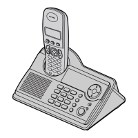
(for KX-TCD530SL)
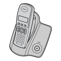
(for KX-TCA151EX)
Note:
After the measuring, sock up the solder of TP.
* : PC Setting () is required beforehand.
The connection of adjustment equipment are as shown in Adjustment Standard (Cordless
Handset) ().
71

 Loading...