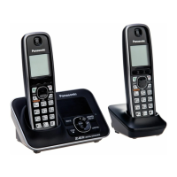
Do you have a question about the Panasonic KX-TG3411BXH and is the answer not in the manual?
Guidelines and precautions for service technicians to prevent fires, injury, or electric shock.
Warning about the risk of explosion if the battery is replaced with an incorrect type.
Information and precautions for using lead-free solder (PbF) during repair work.
Instructions on how to properly discard Printed Circuit Boards, including data deletion.
Explanation of the Frequency Hopping Spread Spectrum (FHSS) technology used in the phone.
Block diagram illustrating the main components and connections of the Base Unit.
Circuit diagram for the telephone line interface, including detection and dialing functions.
Block diagram showing the Radio Frequency (RF) components of the Base Unit.
Detailed explanation of the operational circuits within the Base Unit.
Block diagram illustrating the main components and connections of the Handset.
Block diagram showing the Radio Frequency (RF) components of the Handset.
Detailed explanation of the operational circuits within the Handset.
Explanation of the charging control circuit operation for the Charger Unit.
Details the signal paths for various functions within the system.
Procedures for entering and using the engineering mode for testing.
Steps to reset units to factory settings, erasing user data.
A flowchart to diagnose and identify common issues with the device.
Step-by-step guide on how to disassemble the base unit, handset, and charger.
Step-by-step guide on replacing the LCD screen on the Handset.
Lists the necessary equipment for performing measurements and adjustments.
Instructions on how to set up and connect the JIG for measurements.
Procedures for adjusting Bandgap voltage and frequency on the Base Unit.
Procedures for adjusting Bandgap voltage and frequency on the Handset.
Specifies the adjustment standards and test points for the Base Unit.
Specifies the adjustment standards for the Charger Unit.
Specifies the adjustment standards and test points for the Handset.
Procedures for downloading data after replacing IC or crystal components.
Method for checking the functionality of the handset receiver using a voltmeter.
A table listing frequencies corresponding to different channels.
Step-by-step guide for replacing LLP ICs, including removal and installation.
Method for replacing Flat Package ICs using common tools.
Provides pinout guides for various ICs, transistors, and diodes used in the unit.
General notes and safety notices regarding schematic diagrams.
Detailed schematic diagram of the Base Unit's main circuit.
Schematic diagram of the Base Unit's Radio Frequency (RF) circuit.
Detailed schematic diagram of the Handset's main circuit.
Schematic diagram for the Charger Unit circuit.
Component view of the Base Unit's main printed circuit board.
Component view of the Handset's main printed circuit board.
Component and bottom views of the Charger Unit's printed circuit board.
Exploded view and list of cabinet and electrical parts for the Base Unit.
Exploded view and list of cabinet and electrical parts for the Handset.
Exploded view and list of cabinet and electrical parts for the Charger Unit.
Lists accessories included with the product.
Comprehensive list of replacement parts with part numbers.
| Brand | Panasonic |
|---|---|
| Model | KX-TG3411BXH |
| Category | Cordless Telephone |
| Language | English |





 Loading...