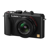
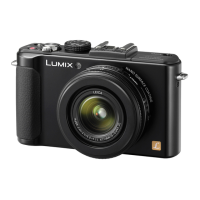
Do you have a question about the Panasonic Lumix DMC-LX5P and is the answer not in the manual?
General safety guidelines for servicing, emphasizing critical parts, protective devices, and proper handling.
Procedure for cold checking leakage current by measuring resistance between plug and exposed metal parts.
Procedure for hot checking leakage current using a specific circuit, voltmeter, and safety limits.
Methods to prevent damage from electrostatic discharge to sensitive components like CCDs and ICs.
Instructions for recycling lithium ion batteries, specific to U.S. users, including contact information.
Manual overview, purpose for understanding and servicing the model, and part ordering information.
Servicing considerations for the lens block, including CCD unit removal and optical tilt adjustment requirements.
Notes on replacing FeRAM (IC6003) on the main P.C.B., requiring specific software for initialization.
Description of lead-free solder (PbF), its composition, and soldering precautions for safe repair.
Notices for service outside USA/Canada, concerning P.C.B. repair limitations and recycle module handling.
How to identify model suffix (NTSC/PAL) by nameplate markings and safety registration marks.
Procedure for initial settings after P.C.B. replacement, with cautions for model suffix selection and data loss.
Explanation of the error code memory function, how it stores errors, and the procedure to display them.
Description of the ICS function, displaying camera settings used when a picture was taken, aiding diagnosis.
List of specific service fixtures and tools required for checking and servicing the unit, including part numbers.
Guidance on necessary adjustments after main P.C.B. replacement, including software requirements and service availability.
Description of service position and list of extension cables used for checking and replacing parts.
Flowchart illustrating the sequence of disassembly for the camera unit, to be followed conversely for assembly.
Shows the physical locations of the various P.C.B.s within the camera assembly for easy identification.
Step-by-step procedure for disassembling various parts and units of the camera, including screw and flex removal.
Instructions for removing the rear case unit, including screw and flex removal steps and screw specifications.
Process for removing the LCD unit, emphasizing careful handling of flex cables, locking tabs, and the LVF jack holder.
Steps to remove the front case unit, including screw removal, flex handling, and screw specifications.
Procedure for removing the top operation unit, with a notice about handling the charging capacitor to prevent damage.
Steps for removing the main P.C.B., including tape, flex cables, locking tabs, and screw removal.
Instructions for removing the lens unit, involving locking tabs, tripod mounts, and associated flex cables.
Procedure for removing the battery P.C.B., including screw and hanging part removal.
How to remove the gyro P.C.B., noting the hanging parts involved and screw specifications.
Guide for speaker removal, with notes on speaker tape and alignment during reinstallation, and rib application details.
Steps for removing the LVF P.C.B., with notices about handling the charging capacitor and shield plate removal.
Procedure for removing the top P.C.B., with notices and installation notes for components like AF Panel Light and locking tabs.
Removal of the flash unit, emphasizing care with the charging capacitor, locking tabs, and rib removal.
Guide for flash P.C.B. unit removal, including cautions, connector, and capacitor discharge procedure.
Removal of the lens ornament unit, including front plate, screws, and associated springs.
Instructions for removing the AF/MF-Aspect FPC, including focus sheet, knobs, and springs, with installation notes.
How to remove the battery case, involving locking tabs and battery out springs, with screw specifications.
Guide for battery door unit removal, detailing shaft and spring components, with installation notes.
Procedure for removing the jack door, with installation notes on screw tightness, surface cleanliness, and image quality.
Details the procedure for disassembling the camera's lens unit, covering various sub-assemblies.
Removal of the zoom motor and lens FPC P.C.B. unit, involving solder points, screws, locks, and photo sensor.
Guide for master flange unit removal, including screws, flex detachment, and grease application notes for installation.
Removal of multiple lens frame units, emphasizing care with flex and avoiding fingerprints on optical surfaces.
Explanation of specific cam and lens frame units removal, involving turning and lifting procedures.
Guide for direct frame and lens frame units removal from the cam frame, involving projection parts and careful lifting.
Description of 2nd and 3rd lens frame units removal from the direct frame, requiring careful handling.
Details the removal of the 1st drive frame unit from the fix frame unit, a crucial step in lens assembly.
Outlines the procedures for assembling the camera lens unit, covering various alignment steps.
Explanation of phase alignment for the 1st lens frame unit and both sides cam frame, involving groove and projection alignment.
Phase alignment for lens frame units, involving marks and grooves for proper assembly of the 2nd 3rd direct frame.
Guide for phase alignment of multiple lens units with the 1st drive frame unit, focusing on mark alignment.
Explanation of phase alignment for various lens units with the 2nd lens frame unit, emphasizing mark alignment.
Details phase alignment for multiple lens units including the 3rd lens frame unit, requiring mark alignment.
Guide for phase alignment of all lens units with the fix frame unit, focusing on mark alignment.
Instructions for installing the master flange unit, including flex insertion, grease application, and screw tightening.
Installation of the zoom motor and lens FPC P.C.B. unit, involving screws, locks, photo sensor alignment, and flex care.
Explanation of CCD unit removal, emphasizing optical tilt adjustment, screw locking glue precautions, and using new screws.
Details focus motor removal, including screw specifications, and grease application notes.
Correct application of grease to lens unit parts, including amounts, tools, and specifying grease type RFKZ0472.
Necessity of adjustments after part replacement, and importance of backing up camera data before disassembly.
Guidance on initial settings release before disassembly to enable automatic camera alignment, noting potential warnings.
How to back up Flash-ROM data before disassembly using non-PC and PC-based methods, detailing file transfer.
Use of a light box, including removing a lens connection ring by loosening hexagon screws for optical adjustments.
Process for electrical adjustments, including startup mode, flag setting, and attention points, executable without a PC.
Steps to execute adjustments like OIS, including flag resets, starting the process, and checking for successful completion.
Critical points and precautions during adjustment, such as not moving components and avoiding button presses.
How to finalize adjustments, including resetting multiple flags, proceeding to the next item, and canceling the mode correctly.
Matrix table detailing necessary adjustments for replaced parts, including flags, tools, setup, and operation steps.
Re-perform initial settings after alignment completion to ensure proper camera operation and confirm adjustment flag status.
Instructions for cleaning the lens and LCD panel, emphasizing avoiding touch and using appropriate cleaning materials.
Safety notices regarding schematic diagrams, component identification marks, and voltage indications for reference.
Standard voltage values measured on the Gyro P.C.B. for diagnostic purposes, indicating pin numbers and power-on values.
Standard voltage values measured on the BAT P.C.B. for diagnostic purposes, indicating pin numbers and power-on values.
Standard voltage values measured on the Flash P.C.B. for diagnostic purposes, indicating pin numbers and power-on values.
Standard voltage values measured on the Top P.C.B. for diagnostic purposes, indicating pin numbers and power-on values.
Illustrates the overall block diagram of the camera, showing interconnections between major components.
Shows the interconnection diagram between various P.C.B.s and units within the camera system, illustrating signal flow.
Provides the schematic diagram for the Gyro P.C.B., detailing its circuitry and connections for analysis.
Presents the schematic diagram for the BAT P.C.B., outlining its circuitry and power connections for troubleshooting.
Shows the schematic diagram for the External LVF unit, detailing its connections and signals for integration.
Provides the schematic diagram for the Flash circuit, illustrating its components and operational flow for servicing.
Details the schematic diagram for the Top P.C.B., including controls and interconnections for system analysis.
Presents the schematic diagram for the CCD Flex P.C.B., showing its connections and signal paths for diagnostic purposes.
Shows the print circuit board layout for the Gyro P.C.B., including component and foil sides for visual reference.
Displays the print circuit board layout for the BAT P.C.B., including component and foil sides for visual reference.
Presents the print circuit board layout for the LVF P.C.B., showing both component and foil sides for visual reference.
Shows the print circuit board layout for the Flash P.C.B., including component and foil sides for visual reference.
Displays the print circuit board layout for the Top P.C.B., focusing on the component side for identification.
Shows the print circuit board layout for the Top P.C.B., focusing on the foil side for connection tracing.
Presents the print circuit board layout for the CCD Flex P.C.B., including component and foil sides for visual reference.
Provides an exploded view of the camera's frame and casing components, with numbered parts for identification.
Shows an exploded view of the camera's lens assembly, detailing various lens components and their arrangement for service.
Illustrates the packing of accessories and parts, showing components like the CD-ROM, battery, and instruction manuals.
Details the packing of accessories, including AC cords and software, specific to different camera models.
| Brand | Panasonic |
|---|---|
| Model | Lumix DMC-LX5P |
| Category | Digital Camera |
| Language | English |


 Loading...