– 19 –– 18 –
4. Wiring diagram
Power switch
TG
2
Capacitor cap
Motor
White
Gray
Black
PinkPink
187
6
5
4
3
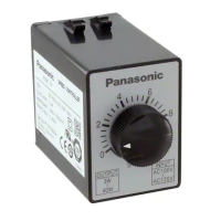
This knob adjusts the rotating speed of the motor from
90 (min
–1
) to 1400/1700 (min
–1
) at 50/60 Hz.
Ground the return circuit to the earth terminal.
Should be class D earthing (100 Ω or less, ø1.6 mm or more).
Ground the return circuit to the earth
terminal.
Should be class D earthing (100 Ω or
less, ø1.6 mm or more).
Tightening torque: 1.0 – 1.5 N·m
Noise filter
Surge absorber
(option)
Molded case circuit breaker
(MCCB): 5 A
<Caution>
Install ground-fault circuit
interrupter in the power
supply.
Power supply
100 V system: 1ø100 – 120 V
200 V system: 1ø200 – 240 V
<Precautions>
The input voltage must be in
the range of rated voltage
compatible with the motor
specification.
Install a noise filter and surge
absorber to protect against
external noise and lightning surge.
Miniature DIN
terminal block
AT7803:
Panasonic
See Section 6.
References.
Capacitor
(supplied with the motor)
For wiring connection of
the capacitor, see the
motor instruction manual.
Wiring diagram
• The motor speed can be adjusted from the speed setting knob on
the controller front panel.
•
The thick continuous lines
represent main circuit. Use conductor
of size 0.75 mm
2
(AWG 18) or larger for the main line.
•
The thin continuous lines
represent signal circuit. Use conductor
of size 0.3 mm
2
(AWG 22) or larger in the signal circuit.
When the distance from the tachometer generator (TG) is long, use
shielded twisted pair cable.
<Caution>
Do not ground the shielding material.