– 27 –– 26 –
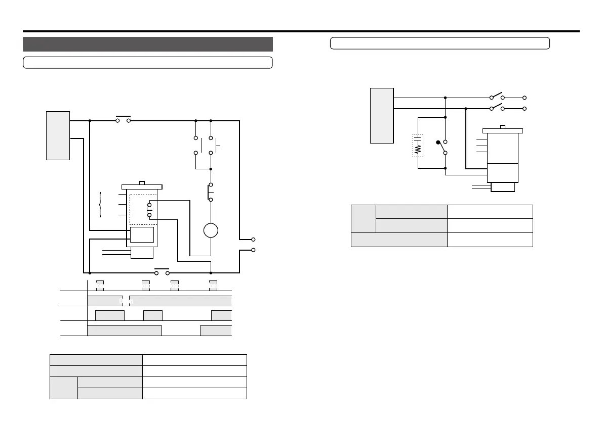
Wiring to electromagnetic brake (40 W or below)
Variable speed motor with electromagnetic brake should be wired as
shown below.
2
1
Pin No.
STOP
C1
Yellow
Yellow
Motor
Brake
Feed motor
rated voltage
R1
RUN
SW9
SW1 100 V supply system AC125 V 5 A or more
SW9 200 V supply system AC250 V 5 A or more
Spark killer R1+C1 DV0P008A (option)
For option, refer to p. 30 onward.
Spark killer
Speed controller
<Precautions>
1. Operate SW9 simultaneously with RUN/STOP switching of other
switches, if any.
2. For remaining wirings, refer to corresponding wiring diagram.
4. Wiring diagram
Peripheral wiring
Motor wiring with cooling fan motor (F) or thermal protector (TP)
The thermal protector (TP) is an automatic reset type. To prevent
hazards caused by restarting of TP, operate it by connecting wiring as
shown below. Don't connect TP directly to the power supply.
SW A Momentary N.O. contact
SW B Momentary N.C. contact
Relay
100 V supply system
AC125 V 5 A or more 3a contact
Ry
200 V supply system
AC125 V 5 A or more 3a contact
2
1
TG
TG(Pink)
TP
Blue or yellow
F(Black)
TP
M
Black
White
Gray
TP
Blue or yellow
Feed
motor
rated
voltage
Ry
F(Black)
SW A
SW B
Ry
ClosedClosed
Open
Run
SWB
ONON ON
Ry
SWA
TP
Closed
Closed Closed Closed Closed
Pin No.
Ry Relay
F
Speed controller
Continue
Motor (M) and
tacho-generator (TC)
should be connected
according to
corresponding wiring
diagram (pp. 20-25).
Once the TP operates, cooling period is required until the operation can start.
Connect the
cooling fan
motor (F)
across pins
(1) and (2) on
the power
terminal.
Open
Closed Closed Closed Closed