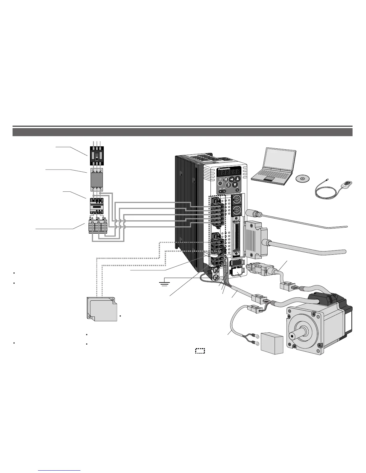
Wiring of the Main Circuit
Ground
(earth)
• Wiring to Connector, CN X3/X4 (option)
(Connection to PC or host controller)
• Wiring to Connector, CN X5
(Connection to host controller)
• Wiring to Connector, CN X6
(Connection to encoder)
• Wiring to
Connector, CN X7
(Connection to
external scale)
• Connection to
the Connector, CN X1
(connection to input power)
• Connection to the Connector, CN X2
(connection to external components)
Junction cable for encoder
Short bar
Junction cable for motor
Junction cable
for brake
DC Power supply for brake
DC24V
(to be supplied by customer)
RB1 (Pin-6)
RB2 (Pin-4)
• Wiring to Connector,
CN X2
(Connection to
motor driving
phase and
ground)
: High voltage
X1
X2
L1 (Pin-5)
L2 (Pin-4)
L3 (Pin-3)
L1C (Pin-2)
L2C (Pin-1)
B3 (5-pin)
RB2 and RB3 to be kept shorted for
normal operation.
When the capacity shortage of
the regenerative resister is found,
disconnect a shorting bar be-
tween RB2 and RB3, then connect
the external regenerative resister
between RB1 and RB2.
(Note that no regenerative resister
is equipped in Frame A and B type.
Install an external regenerative
resister on incombustible materi-
al, such as metal. Follow the same
wiring connection as the above.)
When you connect an external re-
generative resister, set up Parame-
ter No. 6C to 1 or 2.
Handle lever
Use this for connector
connection. Store this
after connection for other
occasions.
(see page for connection.)
Regenerative resistor
(optional)
<Remarks>
When you use an external
regenerative resister, install
an external protective apparatus, such as
thermal fuse without fail.
For resistor value and capacity, refer to the
downloaded Instruction Manual from our Web Site.
Thermal fuse and thermostat are built in to the
regenerative resistor (Option). If the thermal
fuse is activated, it will not resume.
U-phase (red)
V-phase (white)
W-phase (black)
PC (to be supplied by customer)
Setup support software
"PANATERM
®
"
DV0P4460
Console (option)
DV0P4420
3. System Configuration and Wiring
Overall Wiring (Connecting Example of C-frame, 3-phase)

 Loading...