EasyManua.ls Logo

Panasonic NV-DA1 User Manual

Panasonic NV-DA1
209 pages
To Next Page IconTo Next Page
Page #1 background imageLoading...
Page #1 background image
ORDER NO. VMD9807042C8
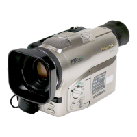
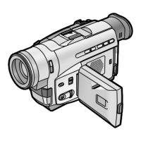
Digital Video Camera/Recorder
NV-DA1
DJ-MECHANISM
EG/B/EN/ENA
SPECIFICATIONS
1998 Matsushita Electric Industrial Co., Ltd. All rights reserved.
Unauthorized copying and distribution is a violation of law.
1. INTRODUCTION
1.1. INTRODUCTION 1
Note 1:
These movie camera uses AC Adaptor VW-AD7E/B/A.
The Service Manual for AC Adaptor is separate volume.
1
Question and Answer IconNeed help?

Do you have a question about the Panasonic NV-DA1 and is the answer not in the manual?

Panasonic NV-DA1 Specifications

General IconGeneral
Media FormatMini DV
Sensor TypeCCD
Optical Zoom10x
ViewfinderColor
Recording MediaMiniDV
Image Sensor1/4 inch
LCD Screen Size2.5-inch
Video Recording FormatDV
Audio Recording Format12-bit/16-bit PCM
InterfaceIEEE 1394 (FireWire)
BatteryLithium-ion

Summary

2. Caution for AC Cord (VJA0940 Type)

2.1. Information for Your Safety

General safety advice, including copyright considerations.

2.2. Caution for AC Mains Lead

2.2.1. Important

Important information regarding wire coloring and terminal connections for safety.

2.2.2. Before Use

Procedure for preparing the equipment for use, including cover removal.

2.2.3. How to Replace the Fuse

3. Service Information

3.1. Service Extension Cables

List and specifications of service extension cables used for connecting various units.

3.2. Service Position

3.3. Preparation for Electrical Adjustment

3.4. Service Mode

3.5. How to Replace the Lithium Battery

Procedure for replacing the internal lithium battery, including disassembly steps.

5. Adjustment Procedures

5.1. Disassemble Flow Chart

Flowchart illustrating the sequence of disassembly steps for cabinet parts and units.

5.2. Disassembly Procedures

5.3. Disassembly Procedures of Lens Unit

7. Wave Form Table

8. Block Diagram

8.1. Overall Block Diagram

High-level block diagram illustrating the main functional units of the device.

8.2. Camera Block Diagram

Detailed block diagram of the camera section, showing its subsystems and interconnections.

8.3. Video Block Diagram

Block diagram focusing on the video signal processing and output stages.

8.4. System Control & Servo Block Diagram

8.5. EVF & LCD Monitor Block Diagram

8.6. Audio Block Diagram

9. Schematic Diagram

10. Circuit Board Ass'y

11.2. Frame & Casing Parts Section (2)

11.3. LCD Parts Section

11.4. Camera Lens Section

11.5. VCR Mechanism Section (1)

11.6. VCR Mechanism Section (2)

11.7. Packing Parts & Accessories Section

12. Replacement Parts List

Related product manuals