Chapter 2 Getting Started — Connecting
54 - ENGLISH
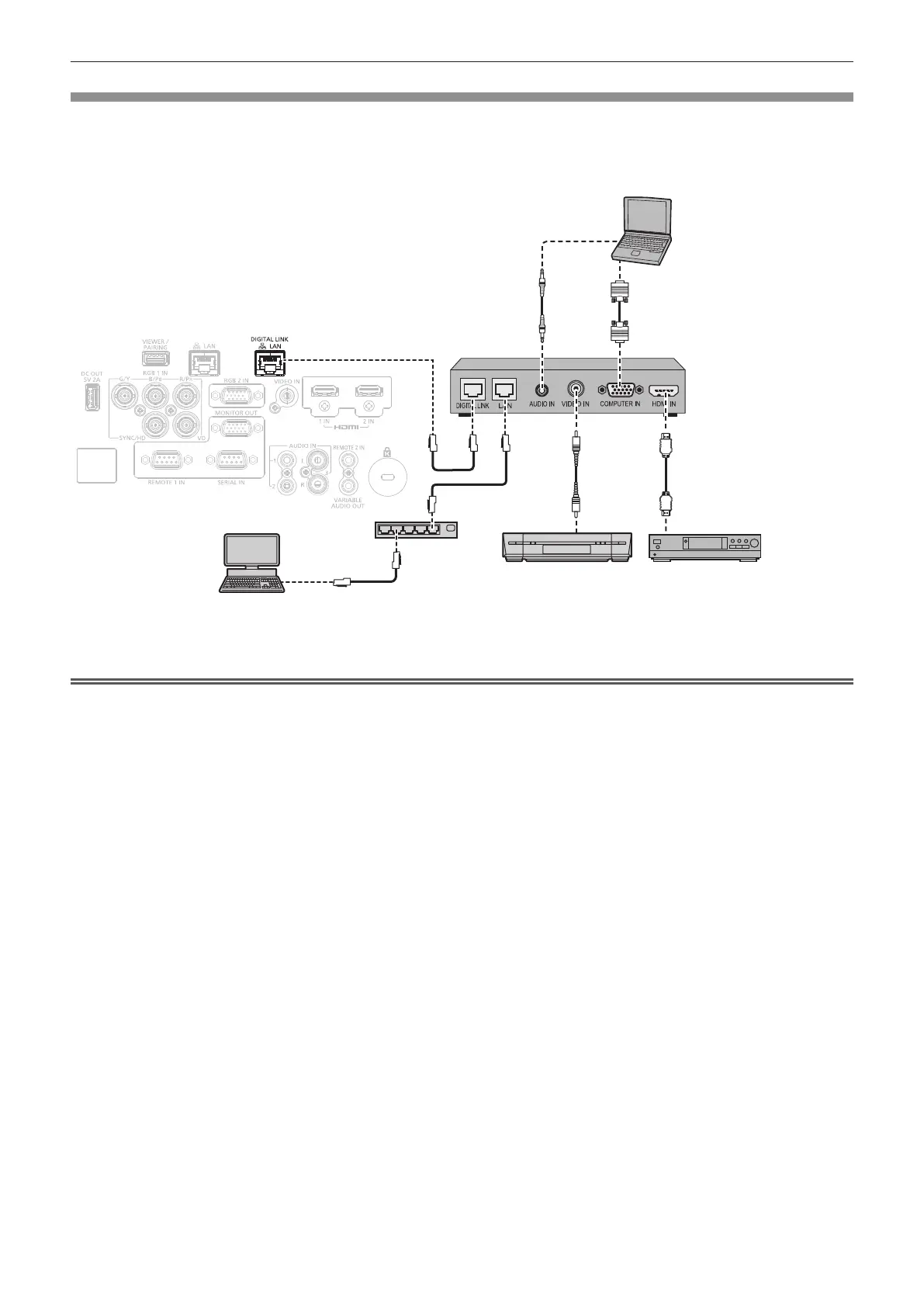
Connecting example using DIGITAL LINK
Twisted-pair-cable transmitter based on the communication standard HDBaseT
TM
such as the optional DIGITAL
LINK output supported device (Model No.: ET-YFB100G, ET-YFB200G) uses the twisted pair cable to transmit
input images, audio, Ethernet, and serial control signal, and the projector can input such digital signal to the
<DIGITAL LINK/LAN> terminal.
Computer
Computer cable (commercially
available)
Projector connecting terminals
Example of twisted-pair-cable transmitter
HDMI cable (commercially
available)
Hub
VCR (with built-in TBC)
Blu-ray disc player
Control computer
*1
*1 Control target is the projector or the twisted-pair-cable transmitter. The control itself may not be possible depending on the twisted-pair-cable
transmitter. Check the operating instructions of the device to be connected.
Attention
f Always use one of the following when connecting a VCR.
g Use a VCR with built-in time base corrector (TBC).
g Use a time base corrector (TBC) between the projector and the VCR.
f The image may be disrupted when nonstandard burst signal is connected. In such a case, connect the time base corrector (TBC) between
the projector and the external devices.
f Ask a qualied technician or your dealer to install the cable wiring between the twisted-pair-cable transmitter and the projector. Image may
be disrupted if cable transmission characteristics cannot be obtained due to inadequate installation.
f For the LAN cable between the twisted-pair-cable transmitter and the projector, use a cable that meets the following criteria:
g Conforming to CAT5e or higher standards
g Shielded type (including connectors)
g Straight-through
g Single wire
f When laying cables between the twisted-pair-cable transmitter and the projector, conrm that cable characteristics are compatible with
CAT5e or higher using tools such as a cable tester or cable analyzer.
When a relay connector is used, include it in the measurement.
f Do not use a hub between the twisted-pair-cable transmitter and the projector.
f When connecting to the projector using a twisted-pair-cable transmitter (receiver) of other manufacturers, do not place another twisted-pair-
cable transmitter between the twisted-pair-cable transmitter of other manufacturers and the projector. This may cause image to be disrupted.
f Do not pull cables forcefully. Also, do not bend or fold cables unnecessarily.
f To reduce the effects of noise as much as possible, stretch out the cables between the twisted-pair-cable transmitter and the projector
without any loops.
f Lay the cables between the twisted-pair-cable transmitter and the projector away from other cables, particularly power cables.
f When laying multiple cables, run them side by side along the shortest distance possible without bundling them together.
f After laying the cable, conrm that the value of [SIGNAL QUALITY] in the [NETWORK/USB] menu → [DIGITAL LINK STATUS] is displayed
in green, which indicates a normal quality. (x page 139)
 Loading...