EasyManua.ls Logo

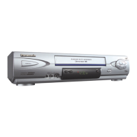
Panasonic PV-4601 A User Manual

Panasonic PV-4601 A
205 pages
To Next Page IconTo Next Page
Page #1 background imageLoading...
Page #1 background image
ORDER NO. MKS9512M303
B3
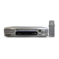
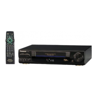
Video Cassette Recorder
PV-4601 A
PV-4601 B
PV-4601-K
PV-4651
PV-4651-K
SPECIFICATIONS
1
Question and Answer IconNeed help?

Do you have a question about the Panasonic PV-4601 A and is the answer not in the manual?

Panasonic PV-4601 A Specifications

General IconGeneral
Video FormatVHS
Recording SpeedSP, LP, EP
Remote ControlYes
ClockYes
TimerYes
ConnectionsAudio
Tape SpeedsSP, LP, EP
Playback SpeedNormal
InputsAudio, Composite video, RF
OutputsAudio, Composite video, RF

Summary

Service Manual

Video Cassette Recorder

Identifies the product covered by the service manual.

SPECIFICATIONS

Lists the technical specifications of the VCR model.

IMPORTANT SAFETY NOTICE

1. SAFETY PRECAUTIONS

Outlines essential safety procedures to be followed during servicing.

1.1. GENERAL GUIDELINES

1.2. LEAKAGE CURRENT COLD CHECK

Procedure for checking leakage current after servicing to prevent shock hazards.

1.3. LEAKAGE CURRENT HOT CHECK

2. PREVENTION OF ELECTRO STATIC DISCHARGE (ESD) TO ELECTROSTATICALLY SENSITIVE(ES)

Guidelines to prevent damage to sensitive electronic components from static discharge.

3. SUMMARY

3.2. HELPFUL SERVICE NOTES AND CAUTIONS

Offers important service notes and cautions for technicians.

3.2.1. Simplified Fault Finding Data

3.2.2. Service Position

Service Position (2)

3.2.3. How to reset all VCR Memory functions

3.2.4. Service Mode

Explains how to enter and exit the service mode for mechanism testing.

3.2.12. How to Remove a jammed Tape

3.3.2. How to remove the VCR Chassis Unit from the frame:

3.3.4. Removal/Installation of Mechanism Chassis to the Main C.B.A.

3.3.8. Service of Capstan Motor Drive C.B.A.

3.3.10. Black Screws on the Chassis

3.3.13. Service of UHF/VHF TUNER/TV DEMODULATOR UNIT

Guidance on servicing the UHF/VHF tuner/TV demodulator unit, noting factory pre-adjustment.

3.3.15. Replacement Procedure for Leadless (Chip) Components

4. ADJUSTMENT PROCEDURES

4.1. MECHANICAL ADJUSTMENT PROCEDURES

Covers mechanical adjustments required for VCR operation.

4.1.1. DISASSEMBLY OF CABINET PARTS

4.1.1.2. DISASSEMBLY METHOD

4.1.2. PROCEDURE FOR CLEANING UPPER CYLINDER UNIT

4.1.3. ADJUSTMENT PROCEDURES

4.1.3.1. REPLACEMENT OF UPPER CYLINDER UNIT

Procedures for removing and replacing the upper cylinder unit.

4.1.3.2. REPLACEMENT OF CYLINDER UNIT

4.1.3.3. CONFIRMATION OF EARTH PLATE UNIT INSTALLATION POSITION

4.1.3.4. POSITION ADJUSTMENT OF TENSION POST (PRELIMINARY)

4.1.3.5. MEASUREMENT AND ADJUSTMENT OF BACK TENSION

4.1.3.6. HEIGHT ADJUSTMENT OF REEL TABLES

4.1.3.7. HEIGHT ADJUSTMENT OF TAPE GUIDE POSTS (PRELIMINARY ADJUSTMENT)

4.1.3.8. TAPE INTERCHANGEABILITY ADJUSTMENT (FINAL ADJUSTMENT)

1. CONFIRMATION OF TAPE TRAVEL

2. CONFIRMATION OF A/C HEAD HEIGHT

Confirmation of A/C head height for proper tape running along the control head.

3. CONFIRMATION OF TILT OF A/C HEAD

4. AZIMUTH ADJUSTMENT OF A/C HEAD

5. HORIZONTAL POSITION ADJUSTMENT OF A/C HEAD

6. CONFIRMATION/ADJUSTMENT OF ENVELOPE OUTPUT

4.1.3.9. ADJUSTMENT OF FG HEAD GAP

4.1.3.10. REPLACEMENT OF CAPSTAN ROTOR OR STATOR UNIT

4.1.3.11. DISASSEMBLY/ASSEMBLY PROCEDURES OF MECHANISM

4.1.3.13. DISASSEMBLY / ASSEMBLY PROCEDURES OF CASSETTE UP ASS'Y

4.1.3.14. ALIGNMENT PROCEDURES OF CASSETTE UP ASS'Y

4.3. ELECTRICAL ADJUSTMENT PROCEDURES

4.3.1. TEST EQUIPMENT

Lists the necessary test equipment for performing electrical adjustments.

4.3.3. ADJUSTMENT PROCEDURES

1. Servo Section

Procedures for adjusting the VCR's servo system.

4.4. LOCATION OF TEST POINTS AND ADJUSTMENT POINTS

5. SCHEMATIC DIAGRAMS

Section containing all schematic diagrams for the VCR.

5.1. Schematic and C.B.A. Diagram Notes

5.2. Capstan Motor Drive Schematic Diagram

Schematic diagram for the capstan motor drive assembly.

5.3. Main I (Power Supply/System Control/Servo/Operation) Schematic Diagram (A, C, D, E)

Schematic diagram for the main board covering power, control, servo, and operation functions.

5.4. Main II (Signal Process/Audio) Schematic Diagram (A, C, D,

Schematic diagram for the main board covering signal processing and audio functions.

5.5. Main I (Power Supply/Signal Process/Audio/System Control/Servo/Operation) Schematic Diagram(B)

5.6. Main II (Signal Process/Audio) Schematic Diagram (B)

Schematic diagram for the main board (Model B) covering signal processing and audio functions.

5.7. UHF/VHF Tuner/TV Demodulator Schematic Diagram(A,C)

Schematic diagram for the tuner/demodulator unit (Models A, C).

5.8. UHF/VHF Tuner/TV Demodulator Schematic Diagram(D,E)

Schematic diagram for the tuner/demodulator unit (Models D, E).

5.9. UHF/VHF Tuner/TV Demodulator Schematic Diagram(B)

Schematic diagram for the tuner/demodulator unit (Model B).

5.10. Hi-Fi Audio Schematic Diagram

Schematic diagram for the Hi-Fi audio circuitry.

5.11. Head Amp Schematic Diagram

Schematic diagram for the head amplifier circuitry.

5.12. Hi-Fi Audio/Video Head Amp Schematic Diagram

Schematic diagram for the Hi-Fi audio/video head amplifier circuitry.

5.13. Interconnection Schematic Diagram

6. CIRCUIT BOARD DIAGRAMS

Section providing diagrams for various circuit boards.

6.1. Power Supply C.B.A. VEPS1002B2(A,B,C)/VPES1002D2(D,E)

6.2. Power Supply C.B.A. VEPS01042G2(B)

Circuit board diagram for the power supply unit (Model B).

6.3. Capstain Motor Drive C.B.A. VEPS02221C1(A,C,D,E)/VEPS02221D1(B)

Circuit board diagram for the capstan motor drive unit.

6.4. Capstain Motor Drive C.B.A. VEPS02232B1(B)

Circuit board diagram for the capstan motor drive unit (Model B).

6.6. Main (Power Supply/Signal Process/Audio/System Control/Servo/Operation) C.B.A. VEPS6002GA12(B)

Circuit board diagram for the main unit (Model B) covering multiple functions.

6.7. Hi-Fi Audio C.B.A.

7. EXPLODED VIEWS

Section containing exploded views of the VCR's mechanical assemblies.

PACKING PARTS AND ACCESSORIES SECTION

8. REPLACEMENT PARTS LIST

Comprehensive list of replacement parts for the VCR.

8.1. MECHANICAL REPLACEMENT PARTS LIST

UNUSED ITEM NUMBERS

8.2. ELECTRICAL REPLACEMENT PARTS LIST

List of electrical components available for replacement.

Special Note:

2. IMPORTANT SAFETY NOTICE

Safety notice regarding components with special characteristics.

8.2.4. Hi-Fi AUDIO C.B.A. NR ( D,E )

9. BLOCK DIAGRAMS

9.1. Overall Block Diagrams

Provides a general overview block diagram of the VCR's main functions.

9.2. Power Supply Block Diagrams

9.4. Video/Normal Audio Block Diagram

Block diagram showing the video and normal audio signal paths.

9.6. Hi-Fi Audio/MTS/SAP Block Diagrams

Block diagrams illustrating the Hi-Fi audio, MTS, and SAP systems.

9.7. System Control Block Diagrams

Block diagrams showing the VCR's system control functions.

9.8. Servo Block Diagrams

Block diagrams illustrating the VCR's servo system.

9.11. Operation Block Diagrams

Hi-Fi AUDIO/MTS/SAP BLOCK DIAGRAM

VII. BLOCK DIAGRAMS

OVERALL BLOCK DIAGRAM

General block diagram of the VCR's overall operation and troubleshooting flow.

OPERATION BLOCK DIAGRAM

POWER SUPPLY BLOCK DIAGRAM

SERVO BLOCK DIAGRAM

SYSTEM CONTROL BLOCK DIAGRAM

VIDEO/NORMAL AUDIO BLOCK DIAGRAM

CAPSTAN MOTOR DRIVE SCHEMATIC DIAGRAM

UHF/VHF TUNER/TV DEMODULATOR SCHEMATIC DIAGRAM (D,E)

Hi-Fi AUDIO SCHEMATIC DIAGRAM (D,E)

Hi-Fi AUDIO/VIDEO HEAD AMP SCHEMATIC DIAGRAM (D,E)

INTERCONNECTION SCHEMATIC DIAGRAM

MAIN I (POWER SUPPLY/SYSTEM CONTROL/SERVO/OPERATION) SCHEMATIC DIAGRAM (A,C,D,E)

MAIN II (SIGNAL PROCESS/AUDIO) SCHEMATIC DIAGRAM (B)

MAIN I (POWER SUPPLY/SYSTEM CONTROL/SERVO/OPERATION) SCHEMATIC DIAGRAM (B)

One Time VCR Setup

To Set Language, Channel and Clock

Step-by-step process for setting language, channel auto set, and clock.

To Replace Channels in Memory

To Set or Reset the Clock

Procedure for setting or resetting the VCR's clock, including power failure recovery.

Playback a Tape

Record On a Tape

One Touch Timer Recording (OTR)

Instructions for setting up a one-touch timer recording.

Copying Your Tapes (Dubbing)

Caution:

Warning regarding copyright infringement from unauthorized copying.

Timer Recording

Cancel a Timer Recording: Recording is in progress

Timer Recording Using VCR Buttons

MTS Broadcast/ VHS Hi-Fi Stereo System

Selecting the Audio Mode for Recording

POWER SUPPLY C.B.A. VEPS01046G2 (B)

CAPSTAN MOTOR DRIVE C.B.A. VEPS02221C1 (A,C,D,E) /VEPS02221D1 (B)

Related product manuals