25
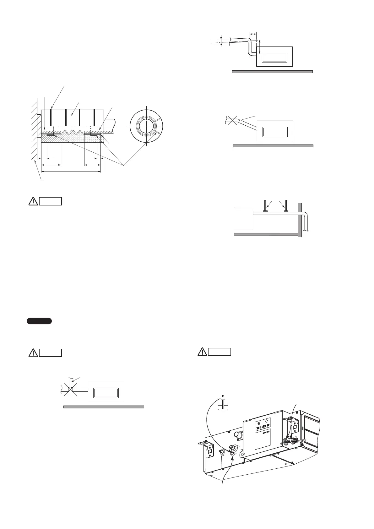
3-22. Installing the Drain Pipe
(1) Prepare standard hard PVC pipe (O.D. 26 mm) for the drain
and use the supplied hose band to prevent water leaks.
(Fig. 3-64)
The PVC pipe must be purchased separately.
The transparent drain part on the unit allows you to check
drainage.
140
25 25
5
5
Fig. 3-64
CAUTION
●
Attach so that the hose band fastener is on the side of the
drain port. (Fig. 3-64)
●
Attach the hose bands so that each is approximately 5 to 25
mm from the end of the supplied drain hose. (Fig. 3-64)
●
Do not use adhesive at the drain connection port on the
indoor unit.
●
Insert the drain pipe until it contacts the socket, as
shown in the figure above, then secure it tightly with the
hose band.
●
Do not use the supplied drain hose bent at a 90° angle.
(The maximum permissible bend is 45°.)
●
Tighten the hose clamps so their locking nuts face in the
horizontal direction.
●
Make sure that the drain port is not a downward gradient
from the joint section (may lead to abnormal noise).
NOTE
Make sure the drain pipe has a downward gradient (1/100 or
more) and that there are no water traps.
CAUTION
●
Do not install an air bleeder as this may cause water to
spray from the drain pipe outlet. (Fig. 3-65-1)
Fig. 3-65-1
●
If it is necessary to increase the height of the drain pipe,
the section directly after the connection port can be
raised a maximum of 500 mm. Do not raise it any higher
than 500 mm, as this could result in water leaks.
(Fig. 3-65-2)
Fig. 3-65-2
●
Do not install the pipe with an upward gradient from the
connection port. This will cause the drain water to flow
backward and leak when the unit is not operating.
(Fig. 3-65-3)
Fig. 3-65-3
●
Do not apply force to the piping on the unit side when
connecting the drain pipe. The pipe should not be
allowed to hang unsupported from its connection to the
unit. Fasten the pipe to a wall, frame, or other support as
close to the unit as possible. (Fig. 3-65-4)
Fig. 3-65-4
3-23. Checking the Drainage
After wiring and drain piping are completed, use the following
procedure to check that the water will drain smoothly. For this,
prepare a bucket and wiping cloth to catch and wipe up spilled
water.
(1) Connect power to the power terminal board (R, S
terminals) inside the electrical component box.
(2) Remove the eyelet cap and through the opening, slowly
pour about 500 cc of water into the drain pan to check
drainage.
(3) Short the check pin (CHK) on the indoor control board and
operate the drain pump. Check the water flow through the
transparent drain port and see if there is any leakage.
CAUTION
Be careful since the fan will start when you short the pin on
the indoor control board.
(4) When the check of drainage is complete, open the check
pin (CHK) and remount the insulator and drain cap onto
the drain inspection port.
Eyelet cap
Wiring port
Water inlet
Fig. 3-66
300 mm or less (not a downward gradient)
500 mm or less
Good
At least 1/100
Upward gradient
Prohibited
Support pieces
Drain port
Twist tie
(4 ties, supplied)
Unit
Drain hose
insulation
(supplied)
Hard PVC pipe
(equivalent to
O.D. 26 mm)
(Field supply)
Position to
fasten hose
bands
Drain hose
(supplied)
Hose band
(2 bands, supplied)
Unit:mm
Air bleeder
Prohibited
Panaindoor336013Eng.indb25Panaindoor336013Eng.indb25 2012/03/2121:07:112012/03/2121:07:11
 Loading...


