EasyManua.ls Logo

Panasonic SA-AK350 User Manual

Panasonic SA-AK350
107 pages
To Next Page IconTo Next Page
Page #1 background imageLoading...
Page #1 background image
n AMPLIFIER SECTION
RMS output power
THD 10%, both channels driven
1 kHz
(Low channel) 112.5 W per channel (3 )
10 kHz
(High channel) 112.5 W per channel (3 )
Total Bi-Amp power 450 W
n FM/AM TUNER, TERMINALS SECTION
Preset station FM 20 stations
AM 15 stations
Frequency Modulation (FM)
Frequency range
87.50 to 108.00 MHz (50 kHz steps)
Sensitivity 4.0 µV (IHF)
S/N 26 dB 2.2 µV
A
ntenna terminal(s) 75 (unbalanced)
A
mplitude Modulation (AM)
Frequency range 522 to 1629 kHz (9 kHz step)
520 to 1630 kHz (10 kHz step)
Sensitivity
S/N 20 dB (at 999 kHz) 560 µV/m
A
udio performance (Amplifier)
Input Sensitivity/ Input Impedance
© 2007 Matsushita Electric Industrial Co. Ltd.. All
rights reserved. Unauthorized copying and
distribution is a violation of law.
SA-AK350GCP
Colour
(S)... Silver Type
A
ux 250 mV, 14.7 k
Music Port input jack
Terminal Stereo, 3.5 mm jack
Sensitivity 100 mV, 4.7 k
Phone jack
Terminal Stereo, 3.5 mm jack
Mic jack
Terminal Mono, 3.5 mm jack
Sensitivity 0.7 mV, 680
n CASSETTE DECK SECTION
Track system 4 track, 2 channel
Heads
Record/playback Solid permalloy head
Erasure Double gap ferrite head
Motor DC servo motor
Recording system AC bias 100 kHz
Erasing system AC erase 100 kHz
Tape speed 4.8 cm/s
Overall frequency response (+3, -6 dB) at DECK OUT
NORMAL 35 Hz to 14 kHz
S/N ratio 50 dB (A weighted)
Wow and flutter 0.18 % (WRMS)
Fast forward and rewind time Approx. 120 seconds with
CD Stereo System
Notes: This model’s CD mechanism changer unit is CRS1. Please refer to the original Service Manual
(Order No. MD0509368C0) for this mechanism.
Specifications
ORDER NO. MD0704047CE

Table of Contents

Question and Answer IconNeed help?

Do you have a question about the Panasonic SA-AK350 and is the answer not in the manual?

Panasonic SA-AK350 Specifications

General IconGeneral
BrandPanasonic
ModelSA-AK350
CategoryStereo System
LanguageEnglish

Summary

Specifications

Amplifier Section

Detailed specifications for the amplifier's output power, THD, and frequency response.

Tuner Section

FM/AM tuner frequency ranges, sensitivity, and antenna terminal specifications.

Cassette Deck Section

Specifications for cassette deck track system, heads, motor, and frequency response.

Disc, USB, General, and System Specifications

Disc Playback Specifications

Details on CD-Audio and MP3 disc compatibility, bit rates, and decoding.

USB Playback Specifications

Information on USB file format support, bit rates, and device compatibility.

General and System Specifications

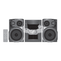
Power supply, dimensions, mass, operating conditions, and system configuration.

Safety Precautions

General Guidelines and Leakage Checks

Essential safety instructions, including leakage current testing procedures for shock prevention.

Before Use, Repair, and Protection

Precautions before operation, during repair, and details on protective circuitry.

Electro Static Discharge (ESD) Prevention

ESD Handling Precautions

Guidelines for safely handling sensitive electronic components to prevent ESD damage.

Traverse Deck Handling Precautions

Traverse Deck ESD Handling

Specific instructions for handling the optical pickup traverse deck to avoid static damage.

Laser Diode Precautions

Laser Diode Safety and Labels

Warnings and safety advice regarding laser diode operation and caution labels.

Lead Free Solder Information

Service Cautions for Lead Free Solder

Guidelines and warnings for servicing equipment using lead-free solder.

Product Accessories

Operating Procedures

Main Unit Key Operations

Explanation of the functions of the main unit's buttons and controls.

Remote Control Operations

Remote Control Key Operations

Description of the functions of buttons on the remote control unit.

New Features

USB Mass Storage Usage

How to connect and play music from USB mass storage devices.

Self-Diagnosis and Special Modes

Service Mode Summary Table

Table summarizing available service modes and their activation methods.

Special Mode Table 1

Detailed table of special modes for diagnosis and operation checks.

Special Mode Procedures

EEPROM Checksum and Reliability Test

Procedures for checking EEPROM checksum and performing reliability tests on the CD changer.

Error Code Displays

Information on error codes displayed during self-diagnosis and their meanings.

Assembling and Disassembling

Disassembly Flow Chart and Locations

Visual guide for disassembling the unit and locating main parts.

Key Disassembly Steps

Step-by-step instructions for disassembling various internal components.

Service Fixtures, Tools, and Positions

Fixtures, Tools, and Positions

Required service fixtures, tools, and recommended positions for PCB checks.

Deck Mechanism Operation Checks

Operation Checks

Procedures for verifying the operation of deck mechanism parts.

Measurement and Adjustments

Cassette Deck Measurements

Methods for measuring and adjusting cassette deck performance parameters.

Voltage and Waveform Charts

PCB Voltage Charts

Tables detailing voltage measurements at various points on PCBs.

Waveform Chart

Visual representations of signal waveforms for diagnostic purposes.

Diagrams

Wiring Connection Diagram

Diagram illustrating the interconnections between different parts of the unit.

Block Diagrams

Functional block diagrams showing the system's architecture and signal flow.

Schematic Diagram Notes

Symbols and Notes

Explanation of symbols, notes, and conventions used in schematic diagrams.

Schematic Diagrams

CD Servo Circuit

Detailed schematic of the CD servo control system.

Main Circuit Diagrams

Comprehensive schematics for the main processing and control circuits.

Panel, Power, Deck, USB Circuits

Schematics for panel, power supply, deck mechanism, and USB interface circuits.

Printed Circuit Board Layouts

PCB Layouts

Visual layouts of the printed circuit boards for component identification.

Component Illustrations

ICs, Transistors, and Diodes

Illustrations and identification of common integrated circuits, transistors, and diodes.

IC Terminal Functions

IC7001 Terminal Functions

Detailed pinout and function description for the IC7001 servo processor.

Other IC Terminal Functions

Pinout and function descriptions for other key integrated circuits.

Exploded Views and Parts List

Cabinet Parts Location

Exploded view showing the location of cabinet and external parts.

Deck Mechanism Parts Location

Exploded view illustrating the arrangement of parts within the deck mechanism.

Replacement Parts List

Comprehensive list of all replaceable parts with part numbers and descriptions.

Related product manuals