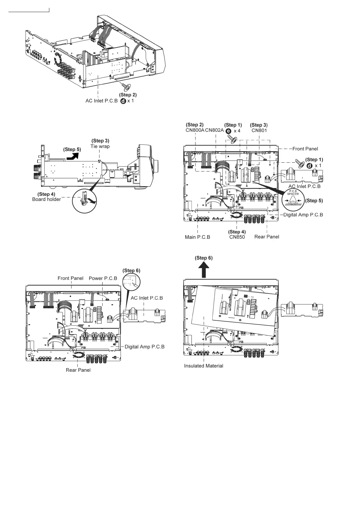
Step 3: Remove tie wrap.
Step 4: Gently pull claw on board holder.
Step 5: Lift up AC Inlet P.C.B..
Caution:
Remember to use tie wraps to tie red/ white wires between (AC
Inlet P.C.B. and Power P.C.B.) to the side of AC Inlet P.C.B.
after repair or troubleshooting.
Step 6: Desolder Red & White wire on the AC Inlet P.C.B
solder side.
Note:
Caution when lift up the AC Inlet P.C.B..
7.11. Disassembly of Power P.C.B.
• Follow the (Step 1) - (Step 4) of item 7.4. - Disassembly of
Top Cabinet.
• Follow the (Step 1) - (Step 5) of item 7.10. - Disassembly of
AC Inlet P.C.B..
Step 1: Remove 5 screws at Power P.C.B..
Step 2: Detach 2 wires on connectors (CN800A & CN802A) at
Main P.C.B..
Step 3: Detach wire on connector (CN801) at Power P.C.B..
Step 4: Detach wire on connector (CN850) at Digital Amp
P.C.B..
Step 5: Press P.C.B spacer as arrow shown and lift up the
Power P.C.B..
Step 6: Lift up the Power P.C.B..
• Replacement of the Power Supply IC and Diode
Step 7: Remove 1 screw (from IC701).
22
-
45
-
45