Do you have a question about the Panasonic SA-MAX370GS and is the answer not in the manual?
Provides essential safety guidelines for servicing the equipment.
Explains the protection circuitry and troubleshooting steps for activation.
Details safety precautions regarding the AC power cord and plug.
Provides cautions and guidance for replacing fuses in the unit.
Lists critical safety components requiring specific replacement parts.
Outlines techniques to prevent damage to sensitive electronic components from static electricity.
Details safety measures when working with the product's laser diode.
Explains the use and properties of lead-free solder in the equipment's construction.
Details precautions for handling the traverse assembly and optical pickup unit.
Instructions for grounding to prevent ESD damage during servicing.
Overview of the service manual's purpose and scope for technicians.
Clarifies what information is included and excluded from this manual.
Illustrates the system's control flow and component interconnections.
Provides explanations for symbols and conventions used in schematic diagrams.
Shows the layout of the main Printed Circuit Board (PCB) on side A.
Shows the layout of the main Printed Circuit Board (PCB) on side B.
Layouts for illumination and FL display PCBs.
Layouts for button, microphone, and USB PCBs.
Layouts for volume jog, illumination jog, and multi control PCBs.
Shows the layout of the Switching Mode Power Supply (SMPS) PCB.
Lists voltage readings for the main PCB, section 1.
Lists voltage readings for the main PCB, section 2.
Lists voltage readings for the main PCB, section 3.
Lists voltage readings for the main PCB, section 4.
Lists voltage readings for the main PCB, section 5.
Lists voltage readings for the main PCB, section 6.
Lists voltage readings for the FL display PCB.
Lists voltage readings for the microphone PCB.
Displays reference waveforms for various test points.
Exploded view showing cabinet part locations for assembly.
Exploded view showing cabinet part locations for assembly.
Exploded view showing cabinet part locations for assembly.
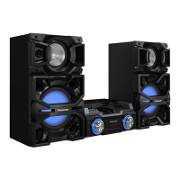
Diagram illustrating the packaging of the SC-MAX370GSK model.
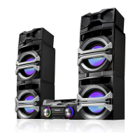
Diagram illustrating the packaging of the SC-MAX770GSK model.
Lists mechanical parts with their reference numbers and descriptions.
Lists electrical components with part numbers and descriptions.
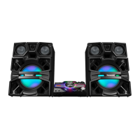
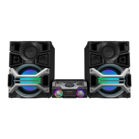
| Total Output Power | 3300W |
|---|---|
| Bluetooth | Yes |
| USB Ports | 2 |
| Preset Equalizer | Yes |
| Power Output | 3300W |
| Frequency Response | 20Hz-20kHz |
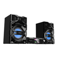
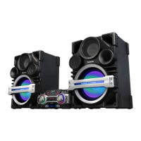
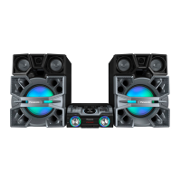
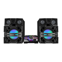
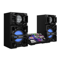
| Type | Mini System |
| Playable Media | CD, USB |
| Audio Input | AUX |
| Speaker Configuration | 2.0 |
| Weight | 4.5 kg (Main Unit) |