Do you have a question about the Panasonic SA-MAX3500PU and is the answer not in the manual?
Important safety notices and general guidelines for servicing the equipment.
Procedure for safely discharging AC capacitors before servicing.
Techniques to prevent damage from electrostatic discharge to sensitive devices.
Safety precautions when handling the laser diode in the optical pickup unit.
Information on lead-free solder used in the equipment and repair cautions.
Methods for grounding worktables and human bodies to prevent static breakdown.
Overview of the service manual's content and ordering information.
Detailed explanation of each button function on the remote control.
Description of key buttons and their functions on the main unit.
Procedure to perform a cold-start or initialize the unit to shipping mode.
Information and procedures for the self-diagnostic mode.
List of error codes related to power supply issues and their solutions.
Flowchart for troubleshooting no power, no display, or no response faults.
Troubleshooting steps for lack of audio output from all speakers.
Troubleshooting guide for no sound when using the USB selector.
Troubleshooting steps for no audio input from microphones.
Procedure for troubleshooting no sound when the tuner mode is selected.
Troubleshooting steps for no audio output in AUX mode.
Troubleshooting FL display showing 'No Play' during USB selection.
Troubleshooting FL display showing 'No Device' for USB selection.
Troubleshooting FL display showing 'No Play' when using memory selector.
Steps to resolve Bluetooth pairing failures and connection issues.
Information about different types of screws used in the unit.
Visual guide outlining the sequence for disassembling unit components.
Diagram showing the placement of major components and PCBs.
Step-by-step instructions for removing the top cabinet.
Detailed instructions for disassembling the main printed circuit board.
Procedure for safely removing the SMPS (Switching Mode Power Supply) PCB.
Steps for detaching and removing the CD mechanism unit.
Procedure for checking the panel, main, and SMPS PCBs during service.
Block diagram illustrating the system control signal flow.
Block diagram showing the audio signal path and components.
Block diagram detailing the power supply circuit and its connections.
Important notes, symbols, and safety warnings for understanding schematics.
Schematic for the main unit's fan LED and Bluetooth connectivity circuits.
Schematic diagram of the main unit's FE (Front End) circuit.
Schematic of the main unit's I/O expansion circuit, part one.
Schematic diagram for the main unit's Micon circuit, section one.
Schematic for the main unit's VREG fan circuit, part one.
Schematic for the main unit's DAMP circuit, section one.
Schematic diagram of the unit's tuner circuit.
Schematic diagram of the unit's panel circuit.
Schematics for button, USB, and CD interface circuits.
Schematic diagram of the microphone input circuit.
Schematic diagram of the SMPS (Switching Mode Power Supply) circuit, part one.
Layout diagram of the main PCB, showing component placement on Side A.
Layout diagram of the main PCB, showing component placement on Side B.
Layout diagrams for the tuner and panel printed circuit boards.
Layout diagrams for button, USB, and microphone PCBs.
Layout diagrams for the SMPS and CD interface printed circuit boards.
Table of voltage indication values for various ICs and modes.
Comprehensive list of electrical components with part numbers for replacement.
List of mechanical parts, including screws, cabinets, and accessories.
Exploded view diagrams showing the assembly of cabinet parts.
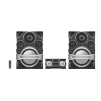
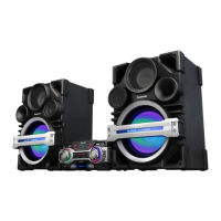
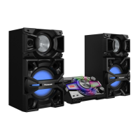
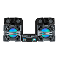
| Type | Mini System |
|---|---|
| USB | Yes |
| Bluetooth | Yes |
| NFC | No |
| CD Player | Yes |
| Radio | FM/AM |
| Preset Equalizer | Yes |
| Karaoke Function | Yes |
| Weight | 8.5 kg |
| Number of Channels | 2 |
| Playable Formats | MP3 |


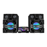
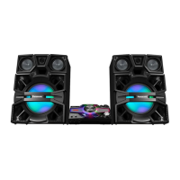
 Loading...