Do you have a question about the Panasonic SA-MAX500LMK and is the answer not in the manual?
General safety guidelines for servicing equipment and handling components.
Precautions before starting repair or adjustment procedures.
Information on the protection circuitry and its operation.
Safety precautions for replacing fuses.
Identifies critical safety parts and the need for manufacturer-specified replacements.
Techniques to prevent damage to ES devices from electrostatic discharge.
Safety precautions when handling the laser diode in the optical pickup unit.
Guidelines for using lead-free solder and legal restrictions.
Specific handling precautions for the optical pickup unit to prevent ESD damage.
Methods for grounding to prevent electrostatic discharge during repair.
Information for service personnel on understanding and servicing the unit.
Step-by-step procedure for updating the unit's firmware.
Information regarding supported media formats for CD and USB.
Explains the function of each button on the remote control.
Explains the function of each button on the main unit.
Instructions for connecting speakers and the AC power cord.
Procedure to initialize the unit to its shipping mode.
Tables detailing various service modes and their operations.
Flow charts for reliability testing of the CD mechanism unit.
Information on entering and using the self-diagnostic mode.
Tables listing error codes and their diagnostic content for troubleshooting.
Procedures for entering and canceling the sales demonstration lock mode.
Identifies the location of key components on the SMPS, Main, and D-Amp PCBs.
Troubleshooting procedures for specific error codes (F61, F76) related to power and amplifier circuits.
Lists various screw types used in the unit.
A flowchart illustrating the sequence for disassembling unit components.
Diagrams showing the location of major components and PCBs within the unit.
Step-by-step instructions for removing the top cabinet.
Step-by-step instructions for removing the front panel unit.
Step-by-step instructions for removing the FL display PCB.
Step-by-step instructions for removing the control PCB.
Step-by-step instructions for removing the volume PCB.
Step-by-step instructions for removing the volume jog LED PCB.
Step-by-step instructions for removing the remote sensor PCB.
Step-by-step instructions for removing the USB PCB.
Step-by-step instructions for removing the microphone PCB.
Step-by-step instructions for removing the LED PCB.
Step-by-step instructions for removing the CD lid.
Step-by-step instructions for removing the rear panel.
Step-by-step instructions for removing the CD mechanism unit.
Step-by-step instructions for removing the main PCB.
Step-by-step instructions for removing the SMPS PCB.
Procedure for replacing the switching regulator IC.
Procedure for replacing rectifier diodes D5702 and D5801.
Procedure for replacing rectifier diodes D5801 and D5803.
Step-by-step instructions for removing the CD interface PCB.
Procedures for checking and repairing multiple PCBs.
Procedures for checking and repairing the main PCB (Side B).
Procedures for checking and repairing the main PCB (Side A).
Procedures for checking and repairing the SMPS PCB.
Block diagram of the servo and system control circuits.
Terminal functions for key ICs used in the system.
Block diagram illustrating the audio signal paths and components.
Block diagram of the power supply unit and its distribution.
Notes and symbols used in the schematic diagrams.
Schematic diagram of the CD servo circuit.
Schematic diagram of the FL display circuit.
Schematic diagram of the volume control circuit.
Schematic diagram of the control and USB interface circuits.
Schematic diagram of the remote sensor circuit.
Schematic diagram of the Switched-Mode Power Supply (SMPS) circuit.
Illustration of the main PCB, showing component layout.
Illustration of the CD servo PCB, showing component layout.
Illustrations of various small PCBs including Memory LED, CD Interface, etc.
Illustration of the D-Amp PCB, showing component layout.
Illustration of the SMPS PCB, showing component layout.
Illustration of the CD Interface PCB, showing component layout.
Chart providing voltage and waveform reference values for testing.
Voltage chart for CD Servo PCB, pins 1-144.
Voltage chart for CD Servo PCB, IC8251, IC8501.
Voltage chart for CD Servo PCB, Q8201.
Voltage chart for Main PCB, ICs IC52, IC2000, IC2001, IC2002, IC2003.
Voltage chart for Main PCB, ICs IC2003, IC2004, IC2005, IC2006, IC2008, IC2010, IC2011, IC2012, IC2014, IC5600.
Voltage chart for Main PCB, transistors Q5603, Q5604, Q2009, etc.
Voltage chart for Main PCB, transistors Q2018, Q2022, etc.
Voltage chart for Panel PCB, ICs IC6000, Q6002, etc.
Voltage chart for D-Amp PCB, ICs IC5000, IC5200, etc.
Voltage chart for SMPS PCB, ICs IC5701, IC5799, etc.
Voltage chart for Mic PCB, IC IC6500.
Table showing waveforms for various ICs, useful for troubleshooting.
Visual identification of common ICs, transistors, and diodes used in the unit.
Detailed terminal functions for key ICs used in the system.
Detailed terminal functions for the main Micro-Processor IC2003.
Exploded view showing cabinet parts and their locations.
Diagram showing the location of cabinet parts.
Diagram showing how the unit is packaged with accessories.
List of mechanical replacement parts with part numbers and descriptions.
| Brand | Panasonic |
|---|---|
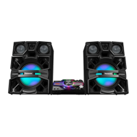
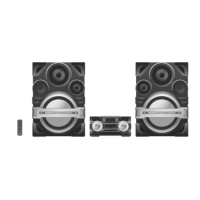
| Model | SA-MAX500LMK |
| Category | Stereo System |
| Language | English |