11 Service Position
Note: For description of the disassembly procedures, see
the Section 10.
11.1. Checking and Repairing of FL
Display P.C.B., Control P.C.B.,
Volume P.C.B., Mic P.C.B. and
USB P.C.B.
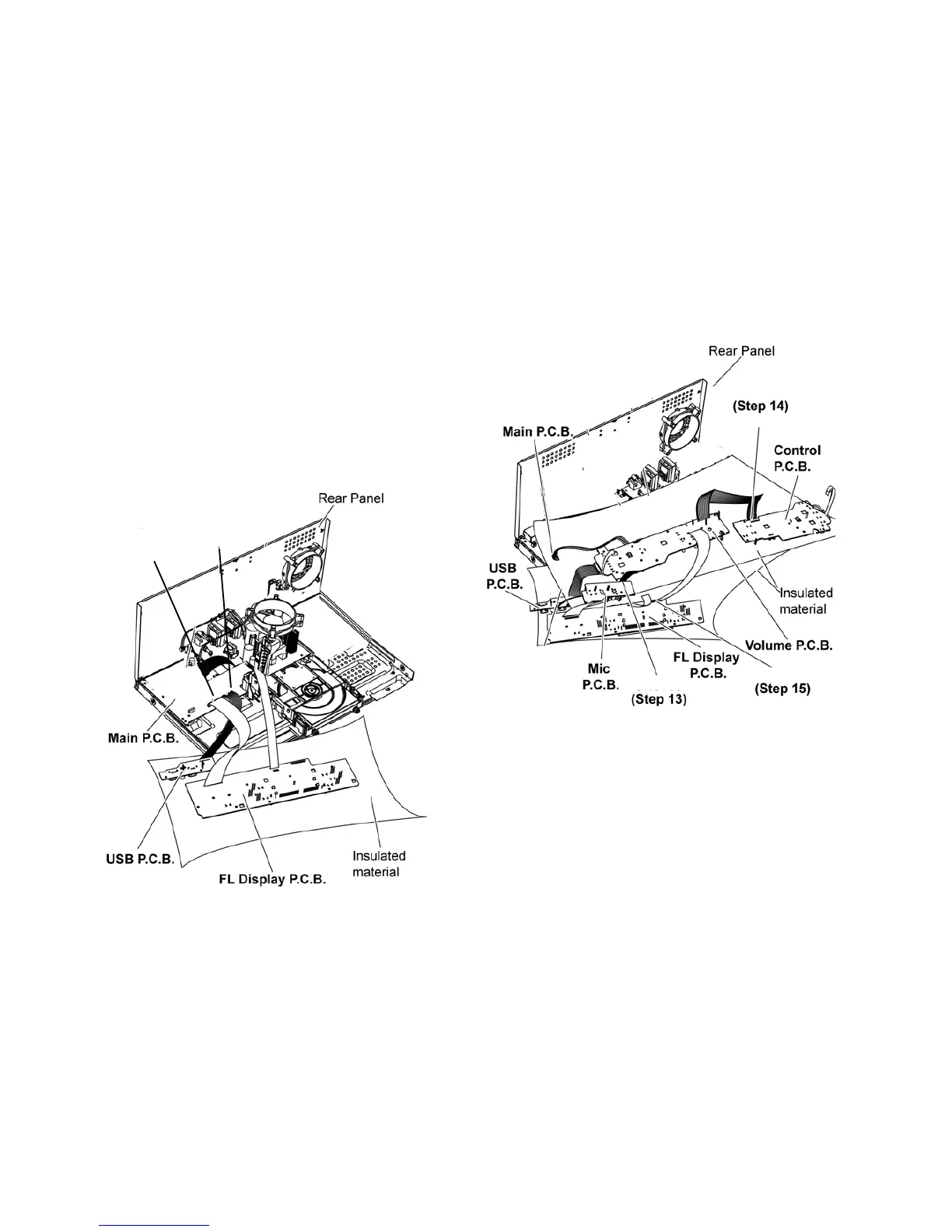
Step 1
Step 11
Step 10
Remove Top Cabinet.
Step 2 Remove Front Panel Unit.
Step 3 Remove FL Display P.C.B..
Step 4 Remove Illumination Button P.C.B..
Step 5 Remove Control P.C.B..
Step 6 Remove Volume P.C.B..
Step 7 Remove USB P.C.B..
Step 8 Remove Mic P.C.B..
Step 10 Attach 11P Cable at a connector (CN2700) on the
Main P.C.B..
Step 11 Attach 30P FFC at a connector (CN2003) on the Main
P.C.B..
Step 13 Attach 8P Cable at a connector (CN6002) on the Mic
P.C.B..
Step 14 Attach 12P Cable at a connector (CN6010) on the
Contro
l P.C.B..
Step 15 Attach 30P FFC at a connector (CN6000) on the FL
Display P.C.B..
Step 17 FL Display P.C.B., Control P.C.B., Volume P.C.B., Mic
P.C.B. and USB P.C.B. can be checked and repaired as dia-
gram shown.
CN2700
CN2003
CN6010
CN6010
CN6002
 Loading...