Do you have a question about the Panasonic SA-MAX7000E and is the answer not in the manual?
Covers general safety instructions and important notices for servicing the equipment.
Procedures for cold and hot leakage current checks to prevent shock hazards.
Steps before repair, adjustment, and protection circuitry operation.
Safety warnings and instructions for the AC power cord, especially for GS models.
Lists critical safety components and their importance for preventing hazards.
Details the functions of each button on the remote control.
Details the functions of controls and buttons on the main unit.
Provides a block diagram illustrating the audio signal path.
Part 1 and 2 of the schematic for the main MICON control circuit.
Part 1 and 2 of the schematic for the main single amplifier circuit.
Schematic diagram detailing the main USB circuit functionality.
Schematic diagram illustrating the main AUX input circuit.
Schematic diagram for the tuner circuit, including AM/FM reception.
Parts 1, 2, and 3 of the schematic for the panel control interface.
Schematic diagram for the microphone input and amplification circuit.
Part 1 and 2 of the schematic for the SMPS (power supply) circuit.
Layout diagrams for the main PCB (Sides A/B) and Tuner PCB.
Layout diagram for the panel control circuit board.
Layout diagrams for Mic, USB, and CD interface PCBs.
Layout diagram for the SMPS (power supply) circuit board.
Exploded views showing the physical location of cabinet parts.
Diagram illustrating the packaging of the unit and included accessories.
List of mechanical parts for replacement, including important safety notices.
List of electrical parts for replacement, including safety and ESD notes.
| Speaker Type | 3-Way |
|---|---|
| Number of speakers | 2 |
| Bluetooth | Yes |
| USB Playback | Yes |
| FM Radio | Yes |
| CD Player | Yes |
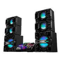
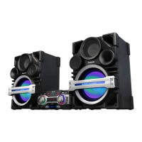
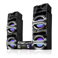
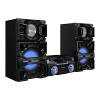
| Type | Mini Hi-Fi System |
| Near Field Communication (NFC) | No |
| Wi-Fi | No |
| Card reader integrated | No |
| Apple docking | No |
| Audio formats supported | MP3 |
| Equalizer | Yes |
| Karaoke | Yes |
| Frequency Response | 20Hz-20kHz |
| Speaker Impedance | 6 Ohms |