EasyManua.ls Logo

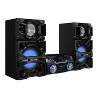
Panasonic SA-MAX4000E Service Manual

Panasonic SA-MAX4000E
31 pages
To Next Page IconTo Next Page
Page #1 background imageLoading...
Page #1 background image
© Panasonic Corporation 2015. All rights reserved.
Unauthorized copying and distribution is a violation of
law.
PSG1505006AE
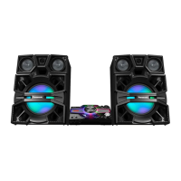
CD Stereo System
Model No. SA-MAX4000E
SA-MAX4000GM
SA-MAX4000GS
Product Color: (K)...Black Type
TABLE OF CONTENTS
PAGE PAGE
1Notes----------------------------------------------------------------- 3
2 Safety Precautions----------------------------------------------- 4
2.1. Before Repair and Adjustment ------------------------- 4
2.2. Power Supply using SMPS Module------------------- 5
2.3. Safety Parts Information -------------------------------- 5
3 Specifications ----------------------------------------------------- 6
4 Schematic Diagram---------------------------------------------- 7
4.1. Main (CD Motor Driver) Circuit -------------------------7
4.2. Main (USB EMMC) Circuit-------------------------------8
4.3. Main (SOC IO Expander) Circuit (1/2)----------------9
4.4. Main (SOC IO Expander) Circuit (2/2)-------------- 10
4.5. Main (Damp) Circuit (1/2)------------------------------ 11
4.6. Main (Damp) Circuit (2/2)------------------------------ 12
4.7. Main (Connector) Circuit (1/2) ------------------------ 13
Notes: Please use this manual together with service manual
Model No.(SA-MAX4000PN), Order no. (PSG1504011CE).
• CD Mechanism Unit, Order No. PSG1303059AE
• Speaker system SB-MAX4000E (For SA-MAX4000E), Order No: PSG1501010CE
• Speaker system SB-MAX4000GS (For SA-MAX4000GM/GS), Order No: PSG1501010CE
Question and Answer IconNeed help?

Do you have a question about the Panasonic SA-MAX4000E and is the answer not in the manual?

Panasonic SA-MAX4000E Specifications

General IconGeneral
BrandPanasonic
ModelSA-MAX4000E
CategoryStereo System
LanguageEnglish

Summary

Notes and Manual Scope

Information Excluded from Manual

Details on information not covered in this service manual.

Information Included in Manual

Details on information provided within this service manual.

Safety Precautions

Pre-Repair Safety Checks

Essential safety procedures and checks before starting repairs.

SMPS Module Power Supply

Information regarding the Switching Mode Power Supply (SMPS) module.

Critical Safety Components

Identification and importance of safety-critical replacement parts.

Specifications

Schematic Diagrams

Main (CD Motor Driver) Circuit

Schematic diagram for the CD motor driver circuit.

Main (USB EMMC) Circuit

Schematic diagram for the USB EMMC circuit.

Main (SOC IO Expander) Circuit (1/2)

First part of the schematic for the SOC IO Expander circuit.

Main (SOC IO Expander) Circuit (2/2)

Second part of the schematic for the SOC IO Expander circuit.

Main (Damp) Circuit (1/2)

First part of the schematic for the Damp circuit.

Main (Damp) Circuit (2/2)

Second part of the schematic for the Damp circuit.

Main (Connector) Circuit (1/2)

First part of the schematic for the Connector circuit.

Main (Connector) Circuit (2/2)

Second part of the schematic for the Connector circuit.

Main (DSP) Circuit

Schematic diagram for the Digital Signal Processor (DSP) circuit.

Main (Tuner AUX) Circuit

Schematic diagram for the Tuner and AUX input circuit.

Main (Vreg Fan) Circuit (1/3)

First part of the schematic for the Vreg Fan circuit.

Main (Vreg Fan) Circuit (2/3)

Second part of the schematic for the Vreg Fan circuit.

Main (Vreg Fan) Circuit (3/3)

Third part of the schematic for the Vreg Fan circuit.

Printed Circuit Board Layouts

Main P.C.B. Side A Layout

Component layout for the main Printed Circuit Board, Side A.

Main P.C.B. Side B Layout

Component layout for the main Printed Circuit Board, Side B.

Parts Lists and Views

Cabinet Parts Location 1

Exploded view of cabinet parts, showing location 1.

Cabinet Parts Location 2

Exploded view of cabinet parts, showing location 2.

Cabinet Parts Location 3

Exploded view of cabinet parts, showing location 3.

Product Packaging Details

Diagram illustrating the product packaging and included accessories.

Mechanical Replacement Parts List

Detailed list of mechanical replacement parts with reference numbers.

Electrical Replacement Parts List

Detailed list of electrical replacement parts with reference numbers.

Related product manuals