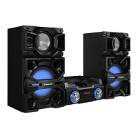
Do you have a question about the Panasonic SA-MAX750LMK and is the answer not in the manual?
Provides essential safety notices, including handling critical parts and using isolation transformers.
Instructs on safely discharging AC capacitors before repair and gradual power restoration after repairs.
Explains conditions for protection circuitry operation and the steps to resolve issues.
Provides cautions and specific fuse types for replacement to ensure safety and proper function.
Lists safety-critical components marked with a symbol, emphasizing the need for manufacturer-specified parts.
Details techniques to minimize component damage from electrostatic discharge (ESD) during handling.
Warns about invisible laser radiation from the pickup lens and provides precautions for safe handling.
Addresses service cautions related to legal restrictions, including lead-free solder requirements.
Provides specific cautions for handling the optical pickup unit to prevent electrostatic discharge damage.
Details grounding procedures for the worktable and human body to prevent static discharge.
States that the manual contains technical information for servicing and clarifies ordering procedures for parts.
Provides a flowchart illustrating the step-by-step process for updating the unit's firmware.
Provides information on compatible media formats, including CD, CD-R/RW, and MP3 disc compatibility.
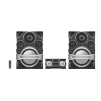
Details the function of each button on the remote control, with corresponding numbers and descriptions.
Explains the function of each button on the main unit of the stereo system, with corresponding numbers.
Provides the procedure to perform a cold-start or initialize the unit to shipping mode.
Describes how to enter Doctor Mode and how to check EEPROM checksum, displaying development year and firmware version.
Presents process flowcharts for aging tests of the CD Mechanism Unit, covering loading, traverse, and combination tests.
Explains how to enter self-diagnostic mode and provides information on error code display.
Lists error codes for various issues, their diagnosis, description, and automatic FL display.
Details how to enter and cancel the sales demonstration lock mode.
Lists different types of screws used in the equipment, along with their part numbers and identification.
Presents a flowchart illustrating the sequence for disassembling various parts and PCBs of the unit.
Shows the locations of major components and printed circuit boards (PCBs) within the unit's chassis.
Provides step-by-step instructions with diagrams for removing the top cabinet, including screw counts.
Details the process of removing the front panel unit, including detaching various cables and FFCs.
Explains how to remove the FL Display PCB, referencing prior disassembly steps and detailing FFC detachment.
Provides instructions for removing the Bluetooth PCB, referencing prior disassembly steps and screw counts.
Details the steps to remove the Illumination Button PCB, including screw removal and cable detachment.
Explains how to remove the Control PCB, starting with removing the control knob and referencing prior steps.
Details releasing catches and detaching FFCs to remove the Control PCB from the front panel unit.
Explains how to lift and remove the Control Jog LED PCB, referencing prior disassembly steps and unit insertion caution.
Details the process of removing the Volume PCB, starting with the volume knob and referencing prior disassembly steps.
Details removing screws, detaching FFCs and cables, and releasing catches to remove the Volume PCB.
Explains how to lift and remove the Volume Jog LED PCB, referencing prior disassembly steps and unit insertion caution.
Provides instructions for removing the Remote Sensor PCB, referencing prior steps and unit connection caution.
Details removing screws and lifting the USB PCB, referencing prior steps and unit seating caution.
Explains how to remove the Mic PCB, starting with the mic knob, detaching cables, and referencing prior steps.
Provides instructions for removing the LED PCB, including screw removal, cable detachment, and releasing catches.
Details the steps to remove the CD lid, including spring removal sequence, lid removal, and guide release.
Provides instructions for removing the rear panel, including screw removal and catch release.
Details removing the Tuner PCB, releasing catches for the fan unit, releasing tabs, and removing the rear panel.
Explains how to remove the CD Mechanism Unit, including screw removal and FFC detachment.
Provides detailed steps for removing the Main PCB, including detaching numerous wires and FFCs.
Details the process of removing the SMPS PCB, including cable detachment, screw removal, and inner fan unit removal.
Explains how to remove the Tuner PCB, including screw removal and FFC detachment.
Provides instructions for removing the CD Interface PCB, including screw removal and desoldering motor pins.
Details steps for checking multiple PCBs, including removal, cable attachment, and checking as per diagram.
Provides steps for checking the Main PCB (Side B), including unit removal and FFC attachment.
Details steps for checking the Main PCB (Side A), including unit removal and cable/FFC attachments.
Provides steps for checking the SMPS PCB, including unit removal, FFC/cable attachments, and PCB upsetting.
Presents the block diagram for the servo and system control section, illustrating component interconnections.
Presents the block diagram for the audio section, showing connections between tuner, Bluetooth, mic, volume, and main PCBs.
Presents the block diagram for the power supply unit, showing AC inlet, transformers, regulators, and control circuits.
Contains important notes regarding schematic modifications, safety notices for components, and units for resistance, capacitance, and inductance.
Presents the schematic diagram for the main circuit, focusing on CD servo, Micon, and damp components.
Provides the schematic diagram for the Bluetooth module, showing connections to the main PCB and firmware download points.
Presents the schematic diagram for the tuner circuit, showing connections to the AM/FM antenna and the main PCB.
Details the schematic diagram for the FL display circuit, showing connections to the display driver and main PCB.
Presents the schematic diagram for the volume circuit, showing connections for volume control, jog, and various buttons.
Provides schematic diagrams for the control and USB circuits, detailing connections for jog dials, buttons, and USB ports.
Details the schematic for the microphone circuit, showing connections for the mic, volume control, and music port.
Presents schematic diagrams for the remote sensor, LED, and illumination button circuits, showing their connections.
Provides the schematic diagram for the SMPS (Switching Mode Power Supply) circuit, detailing AC input, transformers, and output voltages.
Presents schematic diagrams for Control Jog LED, Volume Jog LED, and CD Interface circuits, showing their connections.
Shows the layout of the Main PCB (Side A), indicating component placement and routing.
Shows the PCB layout for the Bluetooth and Tuner modules, including component placement.
Displays the PCB layouts for the FL Display and Volume modules, indicating component locations and connections.
Shows the PCB layouts for Control, Mic, USB, Remote Sensor, LED, and Illumination Button modules.
Presents the PCB layout for the SMPS module, indicating component placement and safety warnings.
Displays the PCB layouts for Control Jog LED, Volume Jog LED, and CD Interface modules.
Provides standard voltage values and waveform examples for troubleshooting and diagnosis.
Provides standard voltage values for the Main PCB across ICs IC2001, IC2002, IC2004, IC2005, IC2006.
Lists standard voltage values for the Main PCB across ICs IC2006, IC2005, IC2006, IC2002, IC2003, IC2008, IC2009, IC2010.
Provides standard voltage values for the Main PCB across ICs IC5002, IC8001, IC5009, IC8001, IC8001, IC8051, IC5002, IC5003, IC5006, IC5008.
Lists standard voltage values for the Main PCB across ICs IC8501, IC8501, IC8501, IC8501, IC8501, IC8501, IC8501, IC8501.
Provides standard voltage values for the Main PCB across ICs IC8501, IC8501, IC8501, IC8501, IC8501, IC8501, IC8501, IC8501.
Lists standard voltage values for the Main PCB across transistors Q2010, Q2011, Q2012, Q2022, Q2024, Q2023, Q3025, Q3101, Q3200, Q3202.
Provides standard voltage values for the Main PCB across transistors Q5012, Q5013, Q5016, Q5017, Q5026, Q5101, Q5102, Q5201, Q5202, Q5301, Q5302, Q5401, Q5402, Q5501, Q5502, Q5601, Q5602, Q5701, Q5702, Q5801, Q5802.
Lists standard voltage values for the FL Display PCB across IC6000, IC6000, IC6000, and Q6001.
Provides standard voltage values for the Volume PCB across QR6100 and IC6100.
Lists standard voltage values for the Mic PCB across IC6300.
Provides standard voltage values for the SMPS PCB across ICs IC1101, IC1102, IC1201, IC1301, IC1401, IC1601 and transistors Q1101, Q1102, Q1103, Q1104, Q1201, Q1202, Q1702, Q1751, Q1803, QR1803.
Presents waveform examples measured at specific ICs during PLAY mode, showing voltage and time divisions.
Shows an exploded view of the unit with numbered parts and references to mechanical replacement parts.
Illustrates the location of cabinet parts and components, with numbers corresponding to the parts list.
Contains a list of electrical replacement parts, including diodes, capacitors, ICs, and transformers.
Lists mechanical replacement parts, including fans, holders, screws, shields, and accessories.
| Type | Mini System |
|---|---|
| Number of Speakers | 3 |
| Bluetooth | Yes |
| CD Player | Yes |
| DVD Player | No |
| USB Port | Yes |
| FM Radio | Yes |
| Subwoofer Included | Yes |
| Remote Control | Yes |