Do you have a question about the Panasonic SA-UX100E and is the answer not in the manual?
Provides general safety guidelines for servicing and handling electrical equipment.
Details precautions before performing repairs or adjustments, including capacitor discharge.
Explains the protection circuitry function and troubleshooting steps when it operates.
Safety advice regarding AC cord usage, fuse replacement, and wiring for specific models.
Lists safety-critical components marked with delta symbol for replacement.
Details the function of each button on the remote control unit.
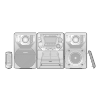
Explains the function of each button and control on the main unit.
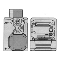
Provides specific instructions for disassembling the rear cabinet, noting changes from the original manual.
Presents the first part of the main control (MICON) circuit schematic diagram.
Presents the second part of the main control (MICON) circuit schematic diagram.
Shows the schematic diagram for the main auxiliary tuner circuit.
Displays the schematic diagram for the main damping circuit.
Illustrates the schematic diagram of the main voltage regulator circuit.
Shows the layout and component placement for the main printed circuit board.
Illustrates the exploded view of cabinet parts and their locations.
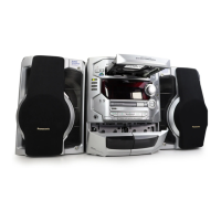
Details the packaging components and arrangement for the product.
Lists mechanical replacement parts with their part numbers, descriptions, and quantities.
Lists electrical replacement parts with their part numbers, descriptions, and quantities.
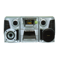
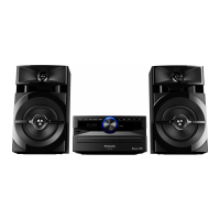
This document provides service information for the Panasonic CD Stereo System, Model No. SA-UX100E, SA-UX100GN, and SA-UX100GS, which features a black color (K). This simplified service manual is based on the SA-AKX100PS (Order No. PSG1608001CE) and should be used in conjunction with it. It covers safety precautions, specifications, control locations, disassembly and assembly instructions, schematic diagrams, printed circuit board layouts, and replacement parts lists.
The Panasonic CD Stereo System is designed to provide high-quality audio playback from various sources. It functions as a compact disc player, an FM tuner, and a Bluetooth-enabled audio system, allowing for wireless streaming from compatible devices. The system also includes a USB port for playing audio files from external storage. The amplifier section delivers powerful stereo sound, making it suitable for home entertainment.
This comprehensive manual ensures that service technicians have all necessary information for safe and effective repair and maintenance of the Panasonic CD Stereo System.
| Brand | Panasonic |
|---|---|
| Model | SA-UX100E |
| Category | Stereo System |
| Language | English |