EasyManua.ls Logo

Panasonic SA-XR55P User Manual

Panasonic SA-XR55P
129 pages
To Next Page IconTo Next Page
Page #1 background imageLoading...
Page #1 background image
n AMPLIFIER SECTION
Rated minimum sine wave RMS power output
20 Hz-20 kHz both channels driven
0.09 % total harmonic distortion
100 W per channel
(6 )
1 kHz continuous power output both channels driven
0.09 % total harmonic distortion 105 W per channel
(6 )
Total harmonic distortion
rated power at 20 Hz-20 kHz 0.09 % (6 )
Power bandwidth
both channels driven, -3 dB 4 Hz-88 kHz
(6 ,0.9%)
Power output each channel driven
0.9 % total harmonic distortion at 1kHz
Front (L/R) 100 W (6 )
Center 100 W (6 )
Surround (L/R) 100 W (6 )
Surround Back (L/R) 100 W (6 )
Load impedance
Front (L/R)
AorB
6-8
A and B
6-8
BI-WIRE 6-8
Center
6-8
Surround (L/R) 6-8
Surround Back (L/R) 6-8
Frequency response
CD, TAPE, TV, DVD, DVD RECORDER,
VCR1, VCR2
4 Hz-88 kHz, ±3 dB
DVD 6CH 4 Hz-44 kHz, ±3 dB
© 2005 Matsushita Electric Industrial Co. Ltd.. All
rights reserved. Unauthorized copying and
distribution is a violation of law.
SA-XR55P
SA-XR55PC
Colour
(S)...............Silver Type
(K)...............Black Type (P only)
Input sensitivity
CD, TAPE, TV, DVD, DVD RECORDER,
VCR1, VCR2
27 mV
(200mV, IHF ’66)
Input impedance
CD, TAPE, TV, DVD, DVD RECORDER,
VCR1, VCR2
22 k
S/N (IHF A)
CD, TV, DVD, DVD RECORDER
(Digital Input)
85 dB
(103 dB, IHF ’66)
Tone controls
BASS
50 Hz, +10 to -10 dB
TREBLE
20kHz,+10to-10dB
Subwoofer frequency response (-6 dB) 7 Hz-200 Hz
n FM TUNER SECTION
Frequency range
87.9-107.9 MHz
Sensitivity 11.2 dBf
(2 µV, IHF ’58)
50 dB quieting sensitivity
MONO 18.3 dBf
(4.5 µV, IHF ’58)
STEREO 38.3 dBf
(45 µV, IHF ’58)
Total harmonic distortion
MONO 0.2%
STEREO 0.3%
S/N
AV Control Receiver
Specification
ORDER NO. MD0504178C1
A1

Table of Contents

Question and Answer IconNeed help?

Do you have a question about the Panasonic SA-XR55P and is the answer not in the manual?

Panasonic SA-XR55P Specifications

General IconGeneral
TypeDigital Receiver
Channels7.1
Power Output100 W per channel
Impedance6 ohms
Input Impedance47 k ohms
Input Sensitivity200 mV
Signal to Noise Ratio100 dB
HDMIYes
InputsHDMI, Optical, Coaxial, Analog
OutputsHDMI
Speaker Impedance6 ohms

Summary

Specifications Overview

Amplifier Section Specifications

Details specifications for the amplifier, including power output, distortion, and impedance.

Safety Precautions and Guidelines

General Safety Guidelines

Outlines essential safety practices for servicing and handling the equipment.

Leakage Current Cold Check Procedure

Procedure to measure leakage current with the unit unplugged for safety.

Leakage Current Hot Check Procedure

Procedure to measure leakage current with the unit powered on for safety.

Operating Instructions

Main Unit Operation

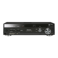
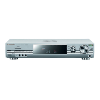
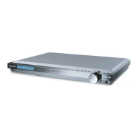
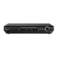
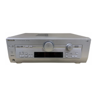
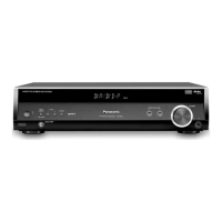
Explains how to operate the main unit, including power and mode settings.

Remote Control Operation

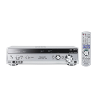
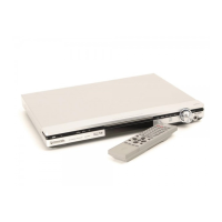
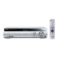
Details the functions and usage of the remote control buttons for operation.

Home Theater Connections

Guides on connecting TV, DVD player, and other devices for home theater setup.

Other Device Connections

Instructions for connecting various audio and video sources like DVD recorders and VCRs.

Disassembly and Component Replacement

Self Diagnosis Display Function

Voltage Measurement and Waveform Chart

Voltage Measurement

Standard voltage values for various test points measured across PCBs.

DSP P.C.B. Voltage Measurement

Standard voltage values for test points on the DSP PCB.

Main P.C.B. Voltage Measurement

Standard voltage values for test points on the Main PCB.

Input P.C.B. Voltage Measurement

Standard voltage values for test points on the Input PCB.

Panel P.C.B. Voltage Measurement

Standard voltage values for test points on the Panel PCB.

Power P.C.B. Voltage Measurement

Standard voltage values for test points on the Power PCB.

Video & Optical P.C.B. Voltage Measurement

Standard voltage values for test points on the Video & Optical PCB.

Component Video P.C.B. Voltage Measurement

Standard voltage values for test points on the Component Video PCB.

Waveform Chart

Visual representations of signal waveforms at key test points for diagnostic reference.

Block Diagram Overview

Schematic Diagrams

DSP Circuit Schematic

Detailed circuit diagram for the Digital Signal Processing section of the receiver.

Power Circuit Schematic

Circuit diagram detailing the power supply and regulation stages.

Video and Optical Circuit Schematic

Schematics for video signal processing and optical input/output circuits.

Component Video Circuit Schematic

Circuit diagram for handling component video input and output signals.

Printed Circuit Board Layouts

Wiring Connection Diagram

Parts Location and Replacement Parts List

Related product manuals