MONO 73 dB
STEREO 67 dB
Frequency response 20 Hz-15 kHz, +1 dB,
-2 dB
Alternate channel selectivity 65 dB
Capture ratio 1.5 dB
Image rejection at 98 MHz 40 dB
Spurious response rejection at 98 MHz 75 dB
AM suppression 50 dB
Stereo separation
1 kHz
40 dB
10 kHz
30 dB
Antenna terminal 75 Ω (unbalanced)
n AM TUNER SECTION
Frequency range 530-1710 kHz
Sensitivity 20 µV, 330 µV/m
Selectivity 55 dB
IF rejection at 1000 kHz 50 dB
n VIDEO SECTION
Output voltage at 1 V input (unbalanced) 1±0.1 Vp-p
Maximum input voltage
1.5 Vp-p
Input/output impedance
75 Ω
S-Video
1 SAFETY PRECAUTIONS 4
1.1. GENERAL GUIDELINES
4
2 Before Repair and Adjustment
5
3 Protection Circuitry
5
4 Handling the Lead-free Solder
5
4.1. About lead free solder (PbF)
5
5 Accessories
6
6 Operating Instructions
7
6.1. Main Unit
7
6.2. Remote Control
8
6.3. Home Theater Connections
9
6.4. Other Connections
14
7 Disassembly and Main Component Replacement Procedures
and Operational Check
17
7.1. Disassembly flow chart
17
7.2. P.C.B. Positions
18
7.3. Disassembly of Top Cabinet.
18
7.4. Checking for the DSP P.C.B. (Side A/B) and Main P.C.B.
(Side A).
19
Input TV, DVD, DVD
RECORDER
Output TV MONITOR
Component Video
Input TV, DVD, DVD
RECORDER
Output TV MONITOR
n GENERAL
Power supply AC 120 V, 60 Hz
Power consumption 135 W
Dimensions (W × H × D)
430 mm × 107.5 mm ×
394 mm
(16-15/16” × 4-7/32” × 15-1/2”)
Mass 4.6 kg (10.1 lb.)
n DIN POWER
1 kHz, T.H. D 1%
2 x 100 W (6 Ω)
Notes:
1. Specifications are subject to change without notice.
Mass and dimensions are approximate.
2. Total harmonic distortion is measured by the digital spectrum
analyzer.
7.5. Disassembly and Checking of Main P.C.B. (Side B)
20
7.6. Disassembly of Tuner Pack and Tuner Extent P.C.B.
20
7.7. Disassembly and Checking of Speaker P.C.B.
21
7.8. Disassembly and Checking of Component Video P.C.B.
21
7.9. Disassembly and Checking of Video & Optical P.C.B.
22
7.10. Disassembly of Rear Panel
22
7.11. Disassembly and Checking of Input P.C.B.
23
7.12. Disassembly of Front Panel
24
7.13. Disassembly and Checking of Panel P.C.B., Volume
P.C.B. and Headphone P.C.B.
25
7.14. Disassembly and Checking of Power P.C.B.
26
8 Self Diagnosis Display Function
27
8.1. Automatically Displayed Error Codes
27
8.2. Display Details
27
8.3. Returning to Normal Display
27
8.4. Overload/Shutdown Detection intenal Condition
27
8.5. Overload/Thermal Detection Display
27
8.6. Activating Self Diagnosis Function (Servicing Mode)
27
8.7. Analog 6.1 CH Output Check Method
28
CONTENTS
Page Page
2
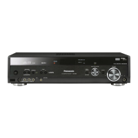
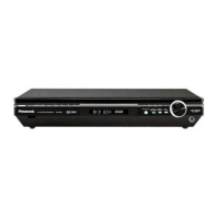
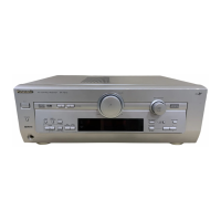
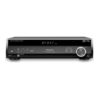
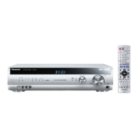
SA-XR55P / SA-XR55PC
 Loading...